Suchen Sie etwas anderes?
Most MTX modems have one or more digital inputs and outputs, and even relays. The GPIO_ parameters allow configuring the behavior of these inputs and outputs. For example, you can configure a digital input so that when it changes state, it will send alarm SMS, or send an MQTT message, or make a voice call, or execute an AT command automatically (or a batch of AT commands) or simply configure it as a pulse counting input.
The case of the digital outputs and relays is analogous. It is possible to configure the behavior to activate an output or relay manually by means of an AT command (sent by serial, SMS, modbus, Telnet, MQTT, …) or to program a time for its activation, or to time the output, or to activate the output if A digital input is activated, or activated if an analog input is out of range, or through a voice call, or based on an astronomical clock, or even based on the value of a Modbus register from a Modbus RTU device that the modem connected to your serial port.
Table of Contents
GPIO_mode0, GPIO_mode1, GPIO_mode2, … , GPIO_mode9
Description: the GPIOs of the MTX modems (the digital inputs and outputs) can be of various types depending on the model of the modem used. On the one hand, a GPIO can only be of type “input”, or it can only be of type “output”, or it can be configured as “input” or as “output” (that is, it can be configured as input or output).
Through this parameter each GPIO is defined as “input” or as “output”. Please refer to the characteristics tables in Annex A of this manual to know the possibilities of each GPIO depending on the MTX modem model.
Possible values:
- input, output
- Default values: depends on the modem model
Additional notes:
- Set the parameter value as “input” if the GPIOx can only be configured as input or if the MTX model allows you to configure the GPIOx as input or output and for the application you want to configure the GPIOx as input
- Set the parameter value as “output” if the GPIOx can only be configured as digital output or if the MTX model allows you to configure the GPIOx as input or output and for the application you want to configure the GPIOx as output
GPIO_config0, GPIO_config1, GPIO_config2, … , GPIO_config8
Description: using these parameters, you can configure the behavior of each of the modem’s GPIOs (digital inputs/outputs). Certain values can be set in the event that the GPIO_modeX parameter is configured as “input” and others in case the GPIO_modeX is configured as “output”.
- Default values: normal
The values shown below are valid when the GPIOx is configured as “input”.
Note that many parameters actually consist of several parameters separated by period and as “;”.
- normal
With this value the GPIO is simply configured as a digital input without any special behavior assigned. This value is useful, for example, when you want to simply query the value of a digital input (for example with the command AT ^ MTXTUNNEL = GETIOS)
Example:
GPIO_mode3: input
GPIO_config3: normal
This example configures GPIO3 as normal input.
- sms;<value>;<timeout>;<mensajeOn>;<mensajeOff>
sms: text indicating that the GPIO is associated with an SMS alarm
<value>: 0,1,2
A 0 indicates that the alarm SMS will be sent when the digital input is not activated
A 1 indicates that the alarm SMS will be sent when the digital input is activated
A 2 indicates that the alarm SMS will be sent when the digital input changes state (from enabled to disabled or vice versa)
<timeout>: 0 … 3600
In the event of an SMS alarm condition, this value indicates the maximum time between shipments. This prevents continuous SMS sending if a digital input changes state continuously by accident.
<mensajeOn>: max. 160 characters (without 😉
In the event of an activated digital input SMS alarm condition, this is the text of the message to be sent.
<mensajeOff>: max. 160 characters (without 😉
In the event of a digital input deactivated SMS alarm condition, this is the text of the message to be sent.
Example:
GPIO_mode3: input
GPIO_config3: sms;2;15;Alarm ON;Alarm OFF
NOTE: This example configures the GPIO3 as an SMS alarm input and will send an SMS message every time the GPIO3 changes state. It will not send more than one SMS every 15 seconds, and will use the texts “Alarm ON” and “Alarm OFF” depending on the value of the digital input.
The telephone numbers used as recipients of the SMS messages are those configured in the ALARM_smsNumberX parameters (being able to specify up to 10).
- counter
With this value the GPIO is configured as a pulse counter. The value of the pulse count can be obtained with the command AT ^ MTXTUNNEL = GETCOUNTER, <IDCounter> or send it using the LOGGER_ parameters to a WEB or MQTT server (see example 7.11 for better understanding).
Example:
GPIO_mode7: input
GPIO_config7: counter
This example configures the GPIO7 as a pulse counter input.
- at;<atOn>;<atOff>
With this value the GPIO is configured as trigger input of an AT command (or batch of AT commands).
<atOn>: AT command to be executed when the digital input is activated
<atOff>: AT command to be executed when the digital input is deactivated
Example:
GPIO_mode2: input
GPIO_config2: at;AT^MTXTUNNEL=EXECUTE,fileon.txt;AT
NOTE: This example configures GPIO2 as an AT command trigger input. When the input is activated, the command “AT ^ MTXTUNNEL = EXECUTE, fileon.txt” is executed (which in turn executes the AT commands contained in that file, see the description of this AT command for more information). If the digital input is deactivated, the command “AT” is simply executed. See Example 8.13 for a better understanding.
- mqtt;<value>;<timeout>
With this value the GPIO is configured to send an MQTT message when the state of that GPIO changes.
mqtt: text indicating that the GPIO is associated with sending MQTT messages
<value>: 0,1,2
0 indicates the MQTT message will be sent when the digital input is not activated
1 indicates that the MQTT message will be sent when the digital input is activated
A 2 indicates that the MQTT message will be sent when the digital input changes state (from enabled to disabled or vice versa)
<timeout>: 0 … 3600 (secs.)
In the event of an MQTT shipping condition, this value indicates the maximum time between shipments. This prevents continuous MQTT message sending if a digital input changes state continuously by accident.
Example:
GPIO_mode3: input
GPIO_config3: mqtt;2;0
This example configures GPIO3 as an input associated with sending MQTT messages. A message will be sent every time the GPIO3 input changes state with no timeout between messages. See Example 8.10 for more information and to view the MQTT message delivery format.
MQTT messages will be sent to the MQTT topic indicated in the MQTT_defaultIOTopic parameter with the Qos specified in MQTT_defaultIOQos.
- call;<value>;<timeout>
With this value the GPIO is configured to make a voice call (without audio) when the state of said GPIO changes.
call: text indicating that the GPIO is associated with making a voice call
<value>: 0,1,2
0 indicates that the call will be made when the digital input is not activated
1 indicates that the call will be made when the digital input is activated
2 indicates that the call will be made when the digital input changes state (from activated to deactivated or vice versa)
<timeout>: 0 … 3600 (secs.)
In the event of a voice call condition, this value indicates the maximum time between calls. This avoids that if a digital input changes state continuously by accident, continuous voice calls are made.
Example:
GPIO_mode3: input
GPIO_config3: call;1;300
This example configures GPIO3 as an input associated with making a voice call. It will be done every time the GPIO3 input is activated (1) and calls cannot be made more frequently within 5 minutes (300 seconds). See Example 8.8 for more information.
- wakeup;<value>
The wakeup mode indicates that the GPIO, configured as input, will activate the 4G/3G/2G session for the configured time (in the parameter GPRS_timeout).
call: text indicating that the GPIO, configured as input, is associated with the start of a 4G/3G/2G session
<value>: 0,1,2
0 means 4G/3G/2G session will take place when the digital input is not activated
1 means 4G/3G/2G session will take place when the digital input is activated
A 2 indicates that the 4G/3G/2G session will be performed when the digital input changes state (from enabled to disabled or vice versa)
Example:
GPRS_timeout: 10
GPIO_mode0: input
GPIO_config0: wakeup;1
This example configures GPIO0 as an input associated with activating the 4G/3G/2G session. When GPIO0 is activated the 4G/3G/2G session will be activated for 10 minutes.
The values shown below are valid when the GPIOx is configured as “output”. Note that many parameters actually consist of several parameters separated by period and as “;”.
- normal
With this value the GPIO is simply configured as a digital output without any special behavior assigned. This value is useful, for example, when you want to simply activate a digital or relay output (for example with the command AT ^ MTXTUNNEL = SETIO, X, Y).
Example:
GPIO_mode8: output
GPIO_config8: normal
This example configures GPIO8 as normal output. See Example 8.14 for further understanding.
- on
With this value the GPIO, configured as output, is always activated.
on: text indicating that the GPIO is an always-on output
Example:
GPIO_mode8: output
GPIO_config8: on
This example configures GPIO8 as always-on output.
- off
With this value the GPIO, configured as output, is always disabled.
off: text indicating that the GPIO is an output always disabled
Example:
GPIO_mode8: output
GPIO_config8: off
This example configures GPIO8 as always-off output.
- time;<HHon>;<NNon>;<HHoff>;<NNoff>
Time mode allows you to specify an on/off time for a digital output/relay (remember that you can also use the “schedule.txt” file to enter more sophisticated schedules).
time: text indicating that the GPIO is a scheduled exit
<HHon>: time for activation of the output (0,…, 23) UTC
<NNon>: minutes for output activation (0… 59) UTC
<HHoff>: time to deactivate the output (0,…, 23) UTC
<NNoff>: minutes for deactivation of the output (0… 59) UTC
Example:
GPIO_mode4: output
GPIO_config4: time;22;00;8;30
This example configures GPIO4 as a scheduled output to activate at 22:00 UTC and deactivate at 8:30 UTC
- timer
The timer mode indicates that the output is timed. In other words, by setting the output as a timer, it is possible to use the command AT ^ MTXTUNNEL = SETOUTPUTTIMER, idOutput, Xseconds so that the GPIO idOutput is activated during Xseconds. See Example 8.3 for a better understanding.
timer: text indicating that the GPIO is a timed exit
Example:
GPIO_mode4: output
GPIO_config4: timer
This example configures GPIO4 as a timed output. Configured in this way a command like AT ^ MTXTUNNEL = SETOUTPUTTIMER, 4.30 would activate the GPIO4 output for 30 seconds.
- digital;<idGPIO>;<inverted>
Digital mode indicates that the status of an output will be related to the value of a digital input. That is, it is possible to make the digital output activate when a digital input is activated or vice versa.
digital: text indicating that the GPIO is an output related to a digital input
<idGPIO>: 0 … 9. ID of the digital input to which it is related
<inverted>: 0,1 0=no inverted, 1=invertied. Inverted implies that the output will activate when the digital input is deactivated, and vice versa
Example:
GPIO_mode0: input
GPIO_config0: normal
GPIO_mode3: output
GPIO_config3: digital;0;0
This example configures GPIO3 as output related to input GPIO0.
When GPIO0 turns on, the GPIO3 output will turn on, and when GPIO0 turns off, the GPIO3 output will also turn off.
This task (output associated with digital input) can also be carried out with the “at” mode of the digital input. See Examples 8.13 (digital input related output) and 8.16 (analog input related output) for more information.
- modbus;<id>;<command>;<reg>;<minVal>;<maxVal>;<minAT>;<maxAT>
The “modbus” mode indicates that the status of an output will be related to the value of a modbus register from an external device. That is, it is possible to make the digital output activate when a modbus register is above a value and deactivate below a certain value.
modbus: text indicating that the GPIO is an output related to a modbus register from an external device
<id>: 1 … 254 modbus address of the modbus slave to interrogate
<command>: 3, 4 modbus read command to use
<reg>: 0 … 65535 modbus register number to read
<minVal>: 0 … 65535 the output will be deactivated when the registry value is equal to or less than this value
<maxVal>: 0 … 65535 the output will be activated when the register value is equal to or greater than this value
<minAT>: AT command to be executed when the registry value is equal to or below <minVal>
<maxAT>: AT command to be executed when the registry value is equal to or above <maxVal>
Example:
GPIO_mode3: output
GPIO_config3: modbus;10;3;1;250;300;;
This example configures GPIO3 as output related to register 1 of the modbus RTU device with address 10 and which is read with the modbus 3 command.
The GPIO3 output will deactivate when the register <= 250 and will activate when the register is> = 300. In this example AT commands are not executed.
- call;<at>
The “call” mode indicates the output is related to a voice call. The output will activate 5 seconds when the modem receives a voice call.
call: text indicating that the GPIO is an output related to an incoming voice call and will activate 5 seconds upon receiving the call
<at>: optional AT command to be executed upon receiving the voice call
Example:
GPIO_mode8: output
GPIO_config8: call;AT+CSQ
This example configures the GPIO8 as an output which will activate for 5 seconds (fixed value) when a voice call is received in the modem. Additionally, the command “AT + CSQ” will be executed.
- astronomical;<MinutosOffsetOcaso>;<MinutosOffsetOrto>
The “astronomical” mode indicates the output is related to the modem’s astronomical clock, activating and deactivating itself from it.
astronomical: text indicating that the GPIO is an output related to the modem’s astronomical clock
<minutosOffsetOcaso>: offset minutes for sunset
<minutosOffsetOrto>: offset minutes for ortho
Example:
MTX_latitude: 41.6333
MTX_longitude: 2.36667
GPIO_mode8: output
GPIO_config8: astronomical;-30;30
This example configures the GPIO8 as an astronomical output, configuring an offset of -30 minutes for sunset (the output will be activated 30 minutes before reaching sunset) and 30 minutes for ortho (the output will be deactivated 30 minutes after ortho).
Note that it is necessary to configure the MTX_latitude and MTX_longitude parameters so that the MTX modem knows how to configure the sunrise and sunset of the day.


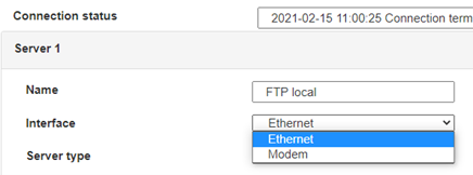
 Enter the “ethernet” or “modem” connection type:
 For an ethernet configuration, make sure the IP parameters are compatible with server access according to the concentrator local network configuration. For an ethernet connection, the configuration must be compatible with the concentrator’s local network topology so that it can access the servers. This configuration is done from the “Networks” configuration page (see section 3.2.2.3: “Networks”).
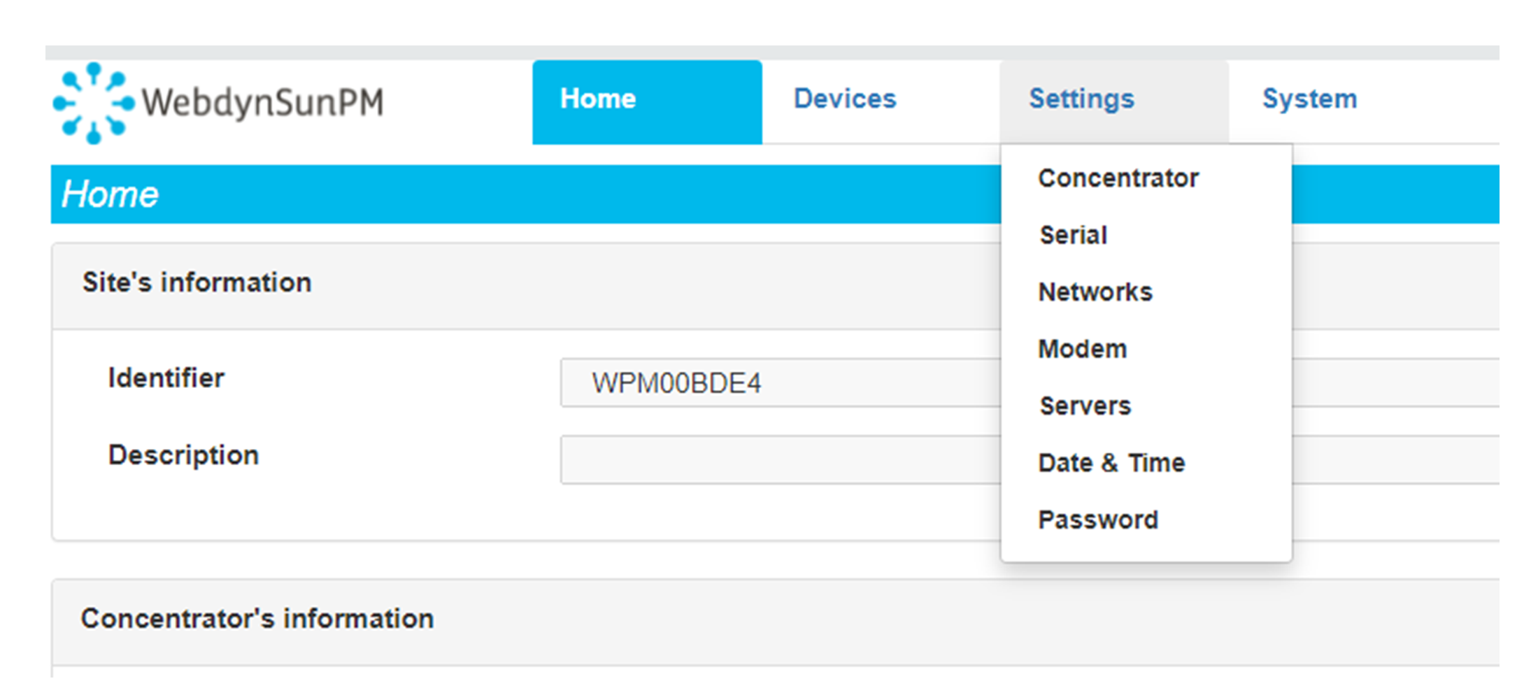
For a modem connection, the modem configuration must be correct before a connection can be set up. This configuration is done from the “Modem” configuration page (see section 3.2.2.4: “Modem”).
The parameters for the servers to be configured are at least the following:
 Therefore the following fields need to be configured: “Interface”, “Type”, “Server type”, “Address”, “Port”, “Login” and “Password”.
The other fields can be left at the default values subject to the directories having been properly created beforehand. See section 3.1.2: “Configuration files” for more details.


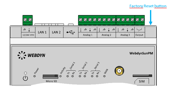
 Wait. The concentrator will reboot using its factory configuration.


