Titan – AN48: Internal LoRa server

Looking for something else?

Scenario Details

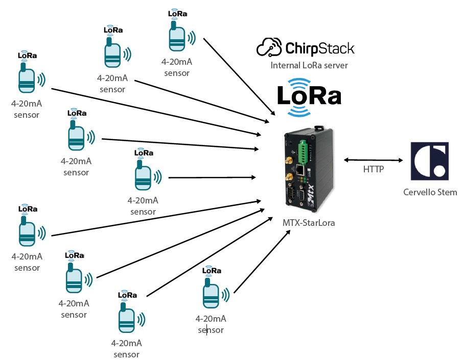
MTX-StarLora is featured as LoRa-4G gateway using external LoRa Server. Check our app note 39.

MTX-StarLora is also featured with integrated Lora Server inside. That means that MTX-StarLora does not depend on external LoRa Servers, like TTN & among others, all the control over other gateways and external Lora devices is done internally. This is perfect to be independent of external parties.

MTX-StarLora it is integrated ChirpStack https://www.chirpstack.io/

Features:

  • End-devices Class A, B and C
  • Adaptative data-rate
  • Live frame-logging
  • Channel (re)configuration
  • Multi-tenant
  • APIs and integration
  • LoRaWAN 1.0 and 1.1 compatible

Description of the Example

This application note shows step by step how to create a LoRa network, with remote LoRa sensors connected and managed by internal LoRa server.

MTX-StarLora will use cellular LTE 4G as WAN interface, will collect all LoRa sensors information and will be sent to end-party cloud integration platform.

Chirpstack LoRa internal server will send LoRa sensor payload datas using HTTPS integration to Cervello platform.

Cervello cloud platform is perfect for this application because the VPI programming featureS as can receive and manage all payloads, filter, and decode this frame payload into telemetries values. Telemetries will be stored and can be displayed in visual tables, graphs…

Cervello will be also used a Device Manager: we can collect DNS information (IP address, time, IMEI, signal strength….) and can be used to group, and control using AT commands

LoRa sensors: we can recommend/tested following nodes:

  • Adeunis
  • RAK
  • URSALINK

Our new MTX-StarLora with Lora capabilities has also all MTX-StarLora-Titan features, so you still can use serial RS232/RS485/USB – Eth-4G gateways, Modbus, Datalogger, VPN, etc making one of the most industrial M2M-IoT featured complete router in the market.

width=910

Please check App note 49 if you want to extend the LoRa network with a slave gateway and have more deep technical aspect on LoRa Server implementation.

MTX-StarLora Configuration

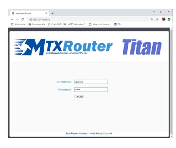
First access to Titan using an Ethernet cable with the default 192.168.1.2 IP Address.

User: admin

Password: admin

width=610

Then, it is needed to configure MTX-StarLora with SIM card network APN information.

WAN -> Basic Setting

Please take care about “Sim PIN” (if SIM card is PIN enabled) and most important ones

“APN”, “Username” and “Password”.

Please keep filled Call Center field as showed, *99***1#

width=1149


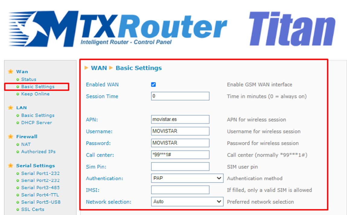
Then click on “SAVE CONFIG” button and important, restart router using menu.

Other->Reboot to allow router restart with new configuration and connect to internet.

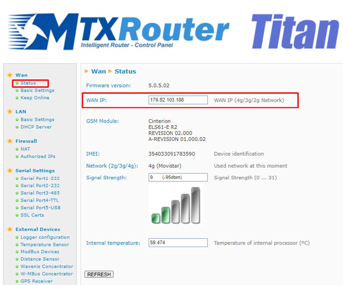
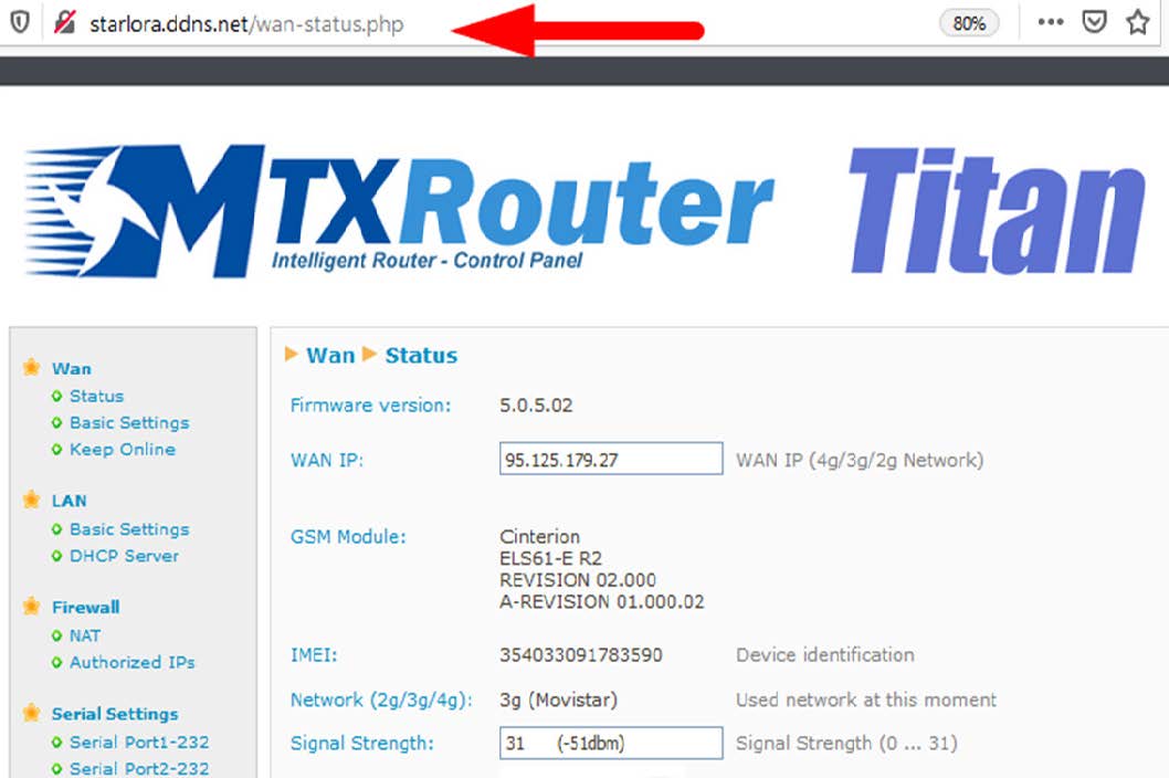
Check WAN IP and keep this value.

width=1113

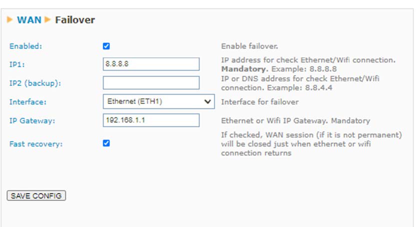
In this example, LAN interface is used as it is connected directly to another Router with internet connection, will use 4G WAN as backup/failure.

Menu: Wan->Basic Setting->Utils.

Click on Failover config button and fill in your case the Gateway IP. If this fail, WAN will be switched to use 4G cellular network.

width=838

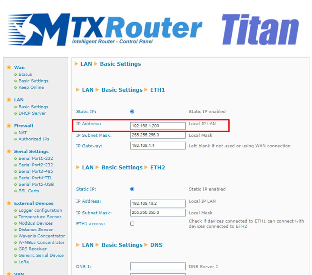
To configure LAN, MTX-StarLora has two Ethernet ports, using number one:

width=1079

To configure the DYNDNS, fill in the following fields:
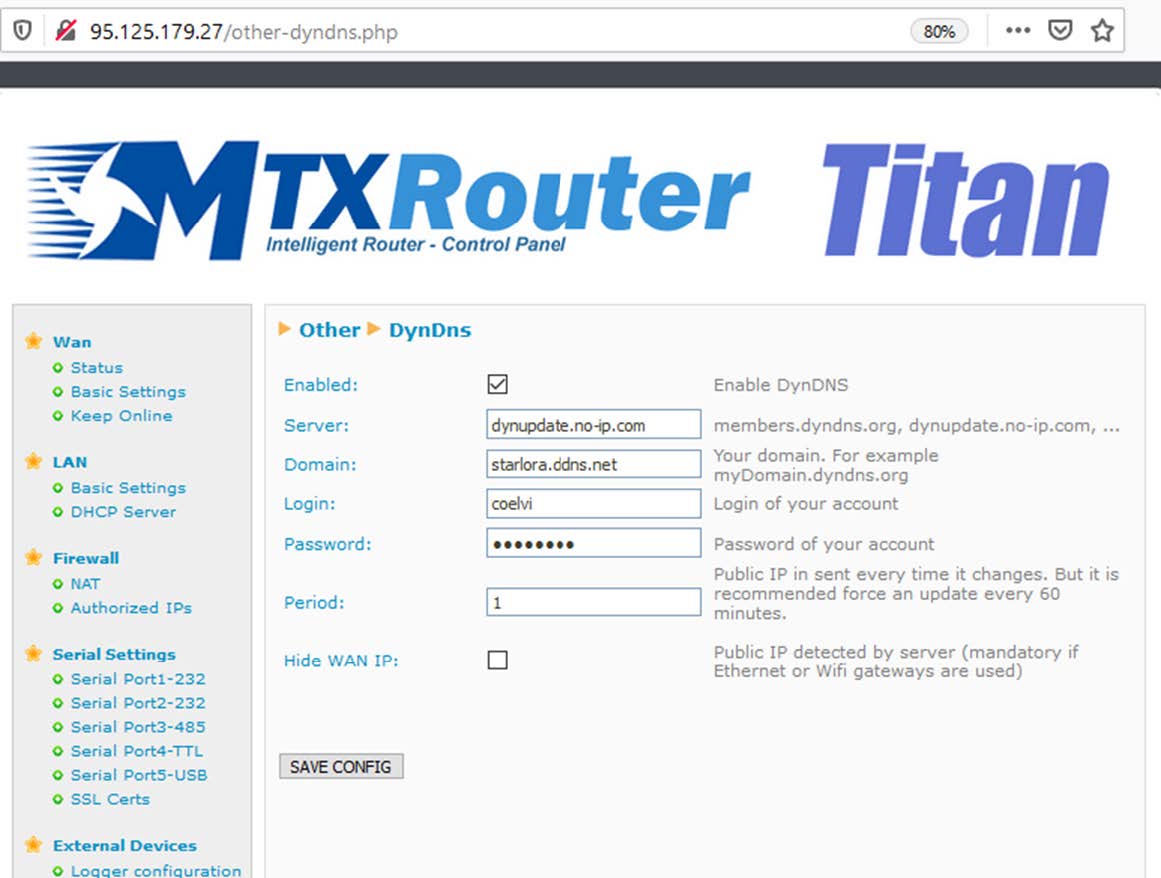
width=1161

Server

Domain

Login

Password

Then, you can FOREVER even if IP public dynamic has been changed, to access TITAN.

width=1058

You can use other MTX-StarLora features as Serial Gateways, Modbus, Logger, MQTT, VPN, SMS…

LoRa Configuration

Please Enable Lora Server.

External Devices – LoRa Gateway it is not needed to use internal LoRa Server.

width=1071

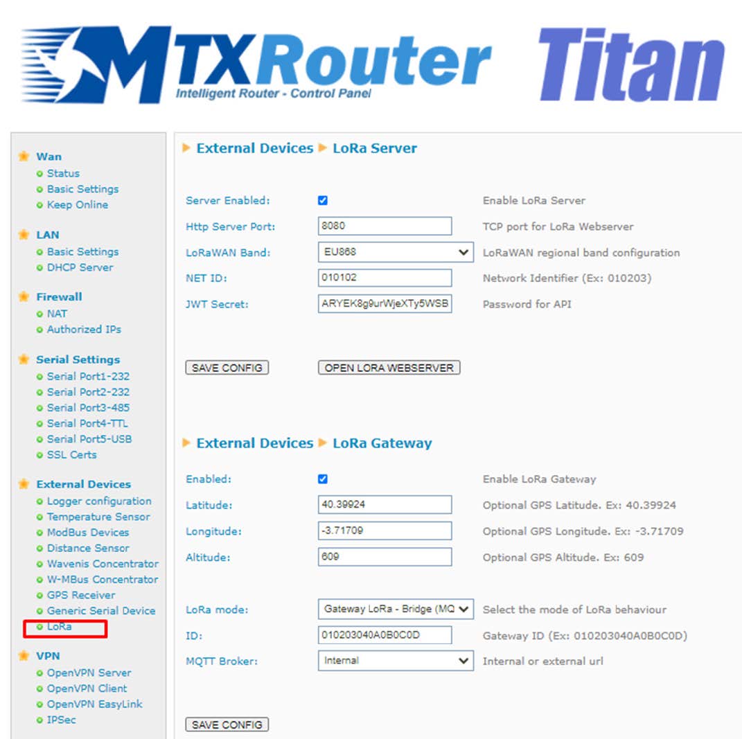
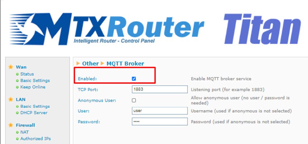
Please fill Other->MQTT Broker to enable listening port 1883

width=1072

Then it is time to open Lora Server.

width=1074

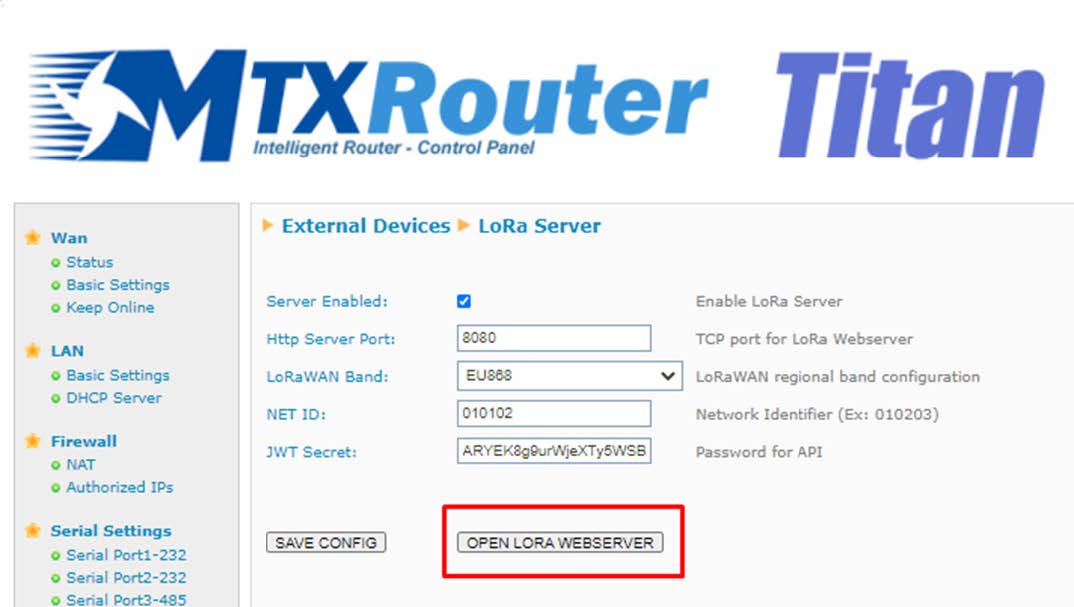
New window will be opened with port 8080

Router address (normally 192.168.1.2:8080)

width=1119

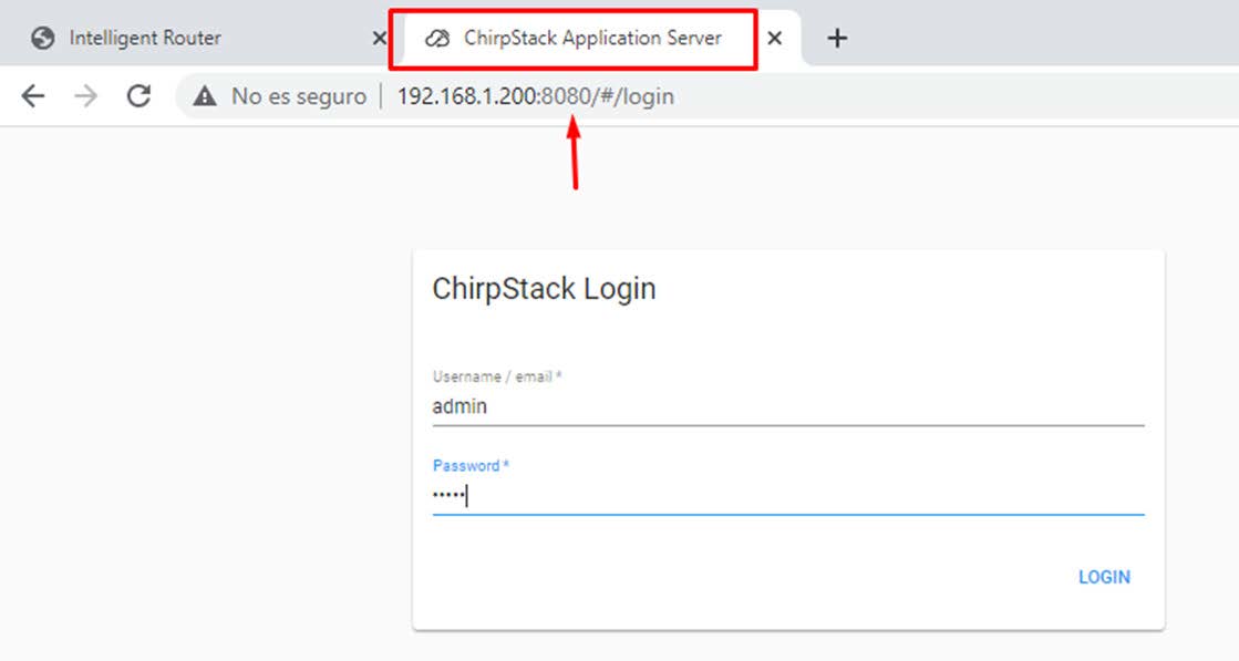
My case http://starlora.ddns.net:8080

ChirpStack Server will be opened.

  • Default user: admin
  • Default password: admin

You can find information, guides, help and community forum at

https://www.chirpstack.io/

and

https://www.chirpstack.io/project/guides/connect-gateway/

ChirpStack Configuration Steps

It is mandatory to follow all this steps to create a Lora Network.

  • Step 1: Add a server
  • Step 2: Add/create a Gateway profile —- connected to 1) Server
  • Step 3: Add/create a Service profile — must be connected to 1) Server
  • Step 4: Add/create a Device profile – must be connected to 1) Server
  • Step 5: Add/create a Gateway – must be connected to 1) Server and 2) Gateway profile
  • Step 6: Add/create an Application — must be connected to 3) Service Profile
  • Step 7: Add Devices – must be connected to 4) Device Profile
  1. Repeat step 7 to add other external devices

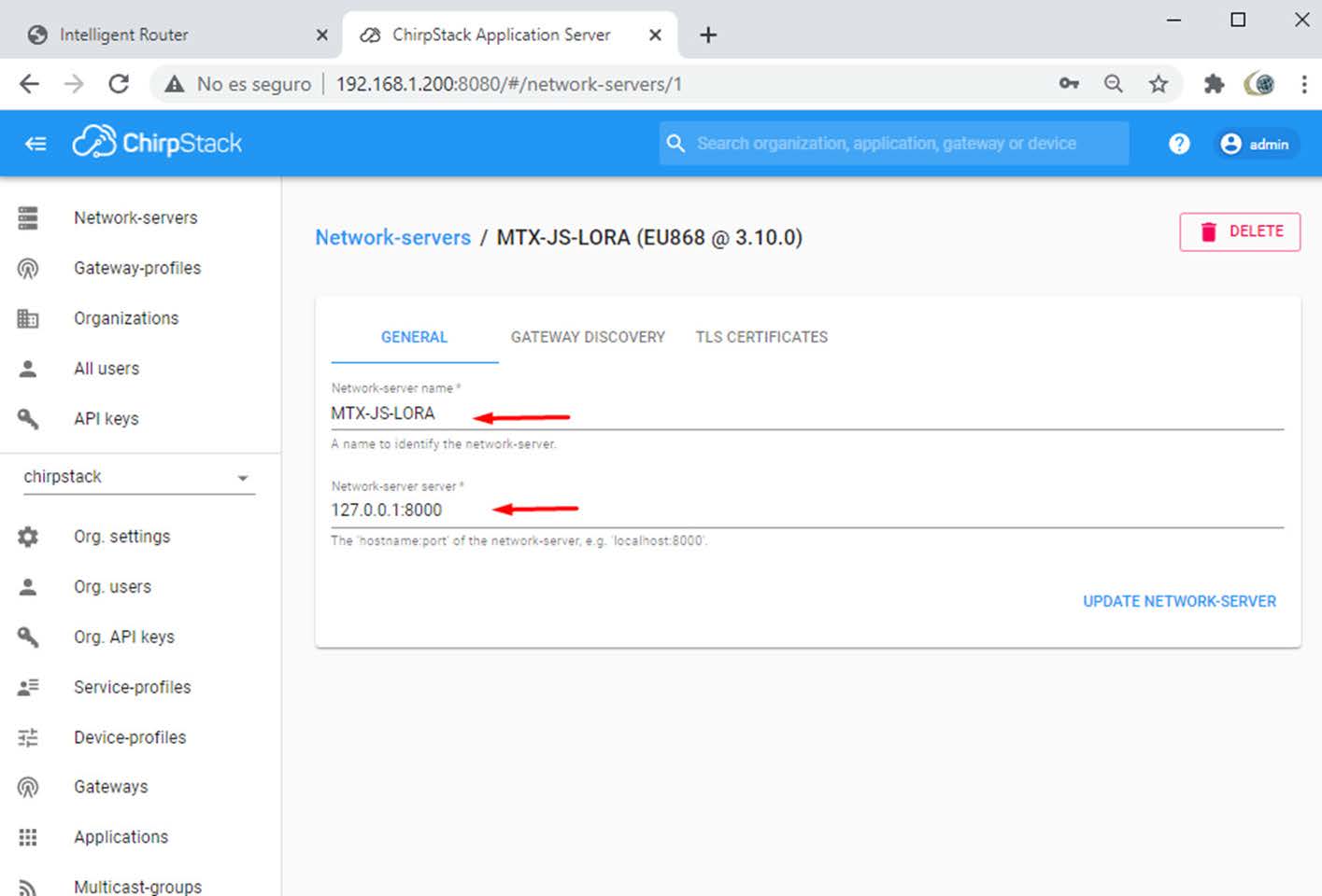
Step 1: Adding a Server

Click on Network Server -> Add

Fill with a string in Network-server-name, example MTX-StarLora-JS-LORA. Fill with a string in Network-server server 127.0.0.1:8000.

width=1415

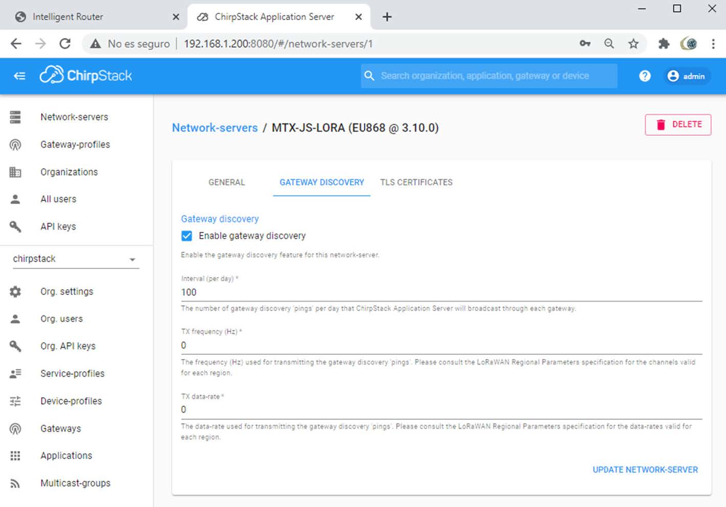
Fill Gateway Discovery as follow:

width=1418

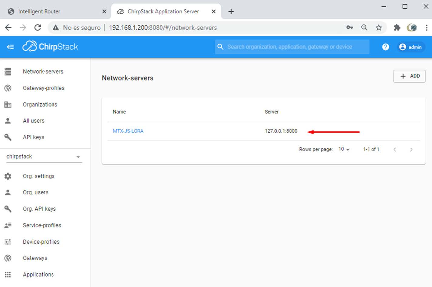
Check if Network Server has been created:

width=1425

Step 2: Adding/Creating a Gateway Profile

Click on Gateway-profiles:

width=1644

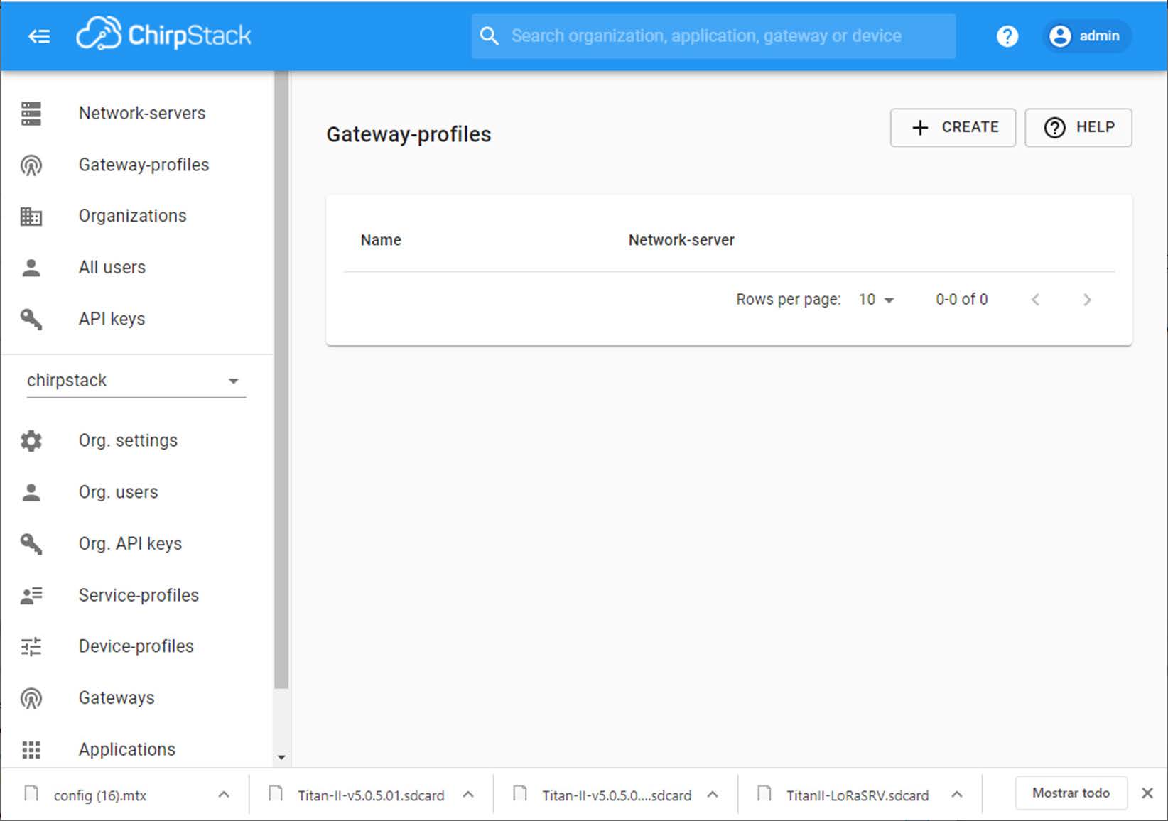
And click on create:

width=1423

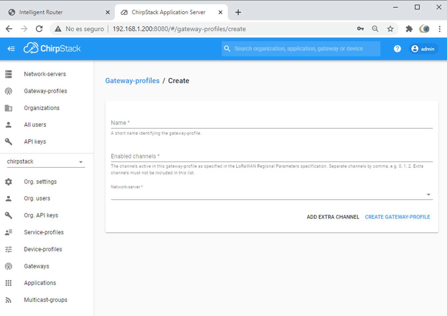
Fill some string name for the Gateway profile and use your Network Server created in step 1.

width=1441

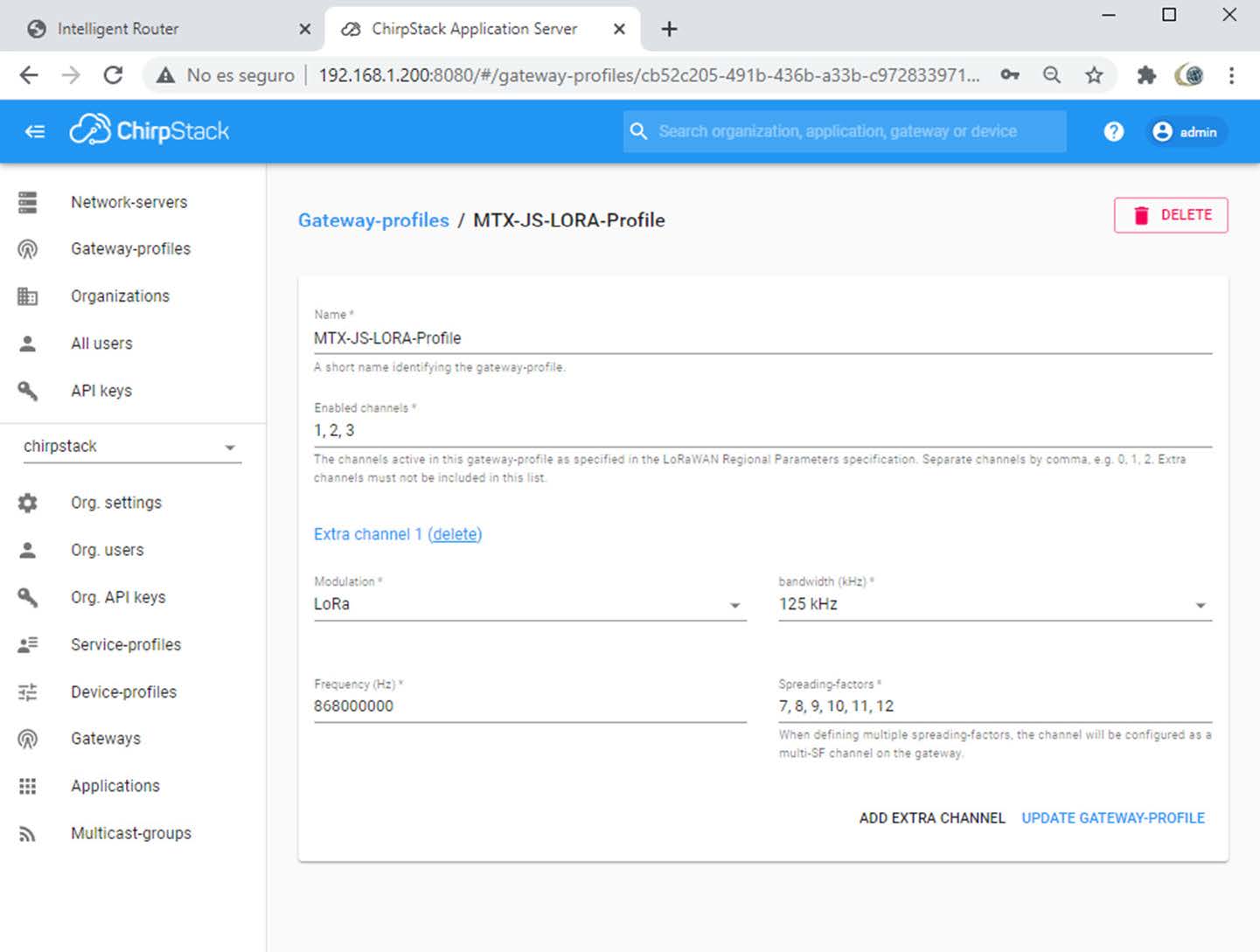
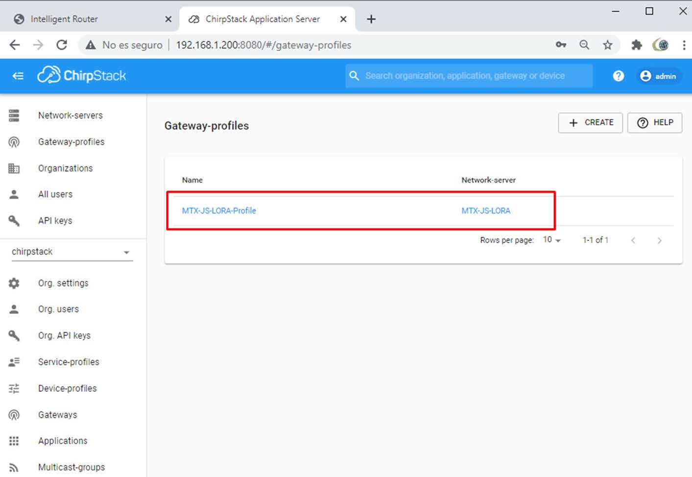
Check if Gateway Profile is linked to Network Server.

width=1413

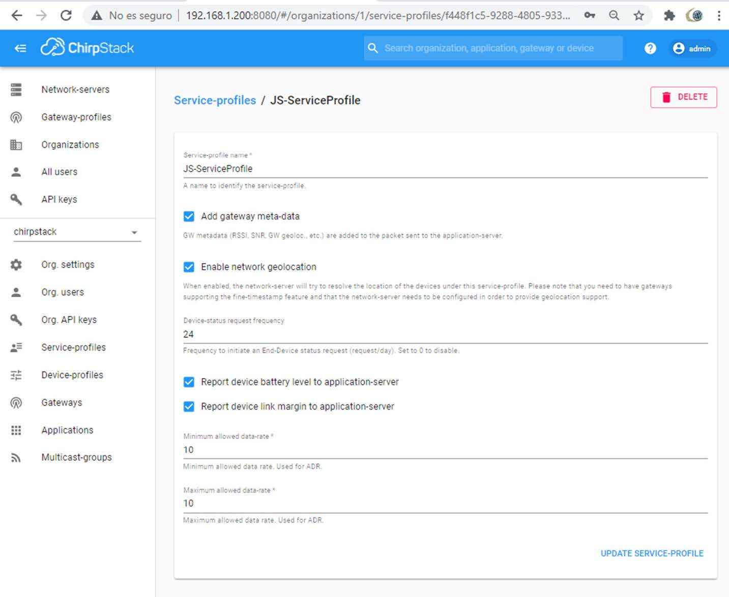
Step 3: Adding/Creating a Service Profile

Click on Service-profiles:

width=991

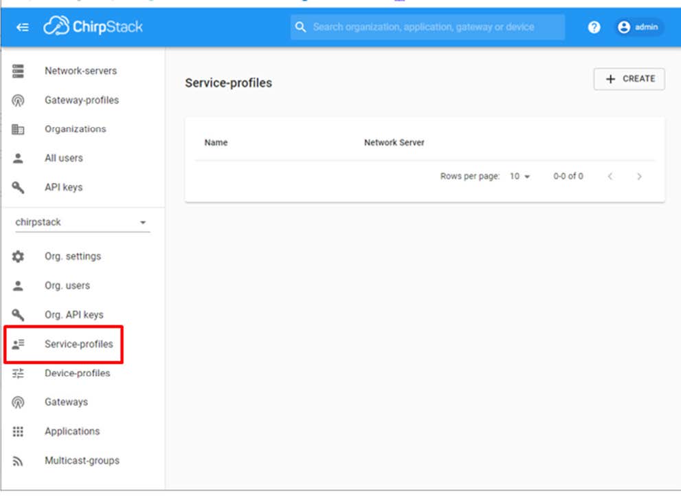
Fill with your Step 1 Network Server and Step 2 Service Profile names. Other fields please read Chirpstack documentation.
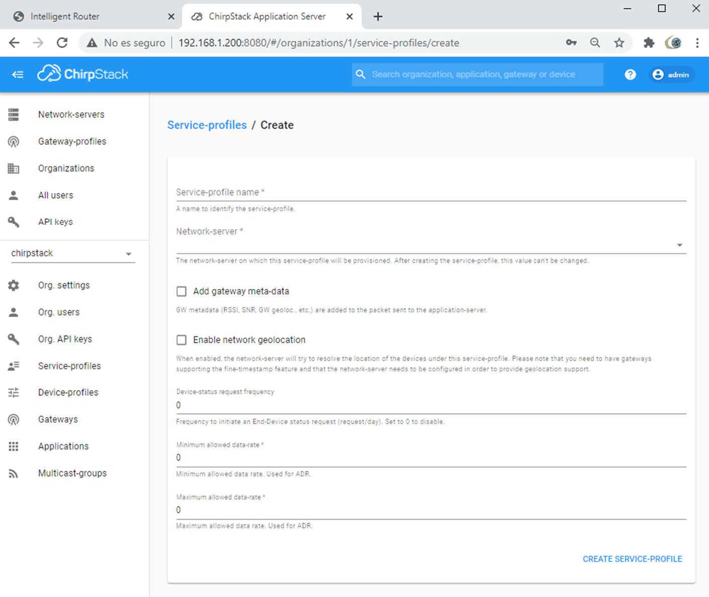
width=1411

As an example:

width=1433

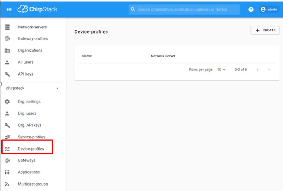
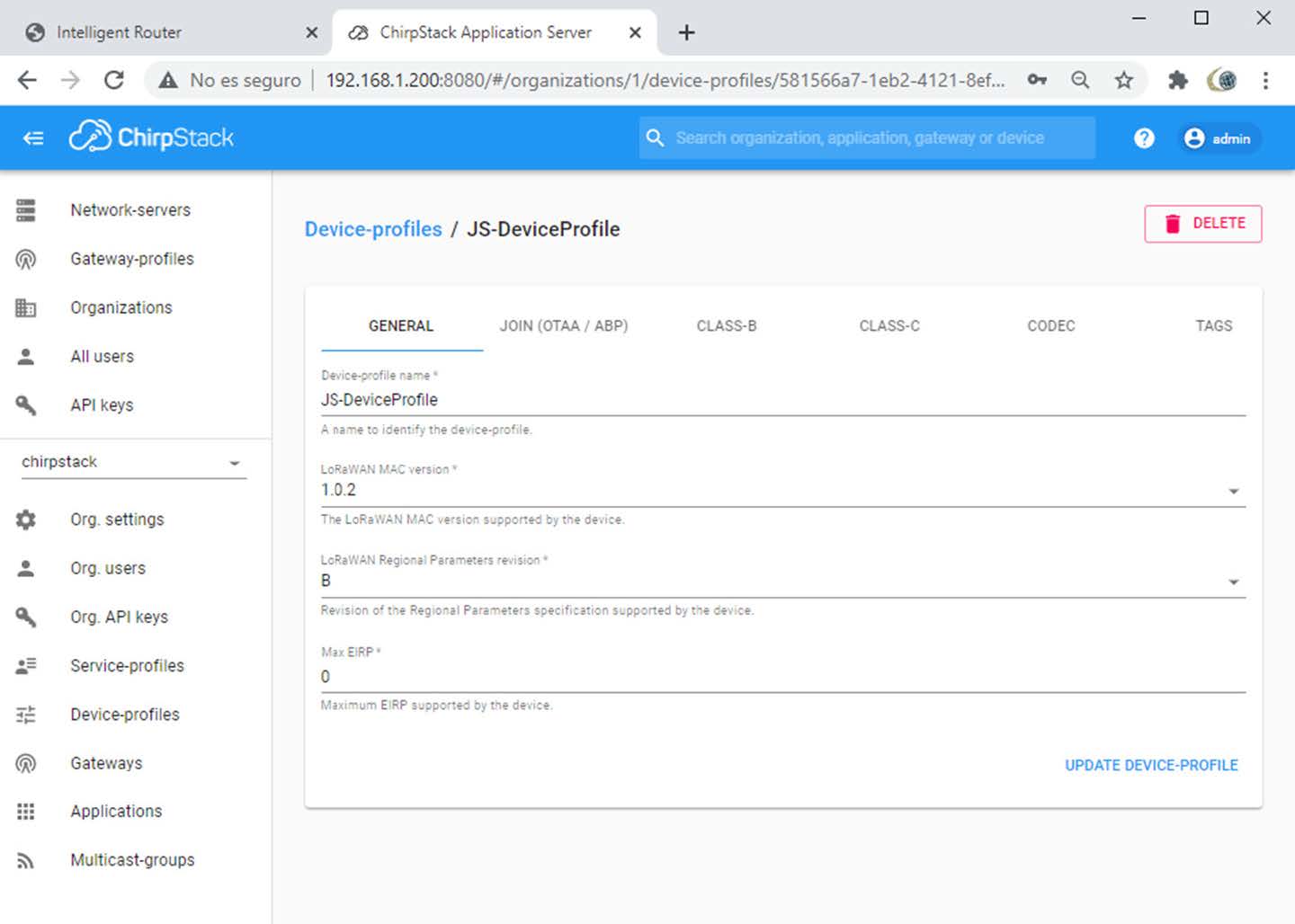
Step 4: Adding/Creating a Device Profile

Click on Device-profiles:

width=983

And fill a name for Device-profile-name (mandatory)

Check your LoRaWan MAC version and other parameters as your LoRa scenario.

width=1440

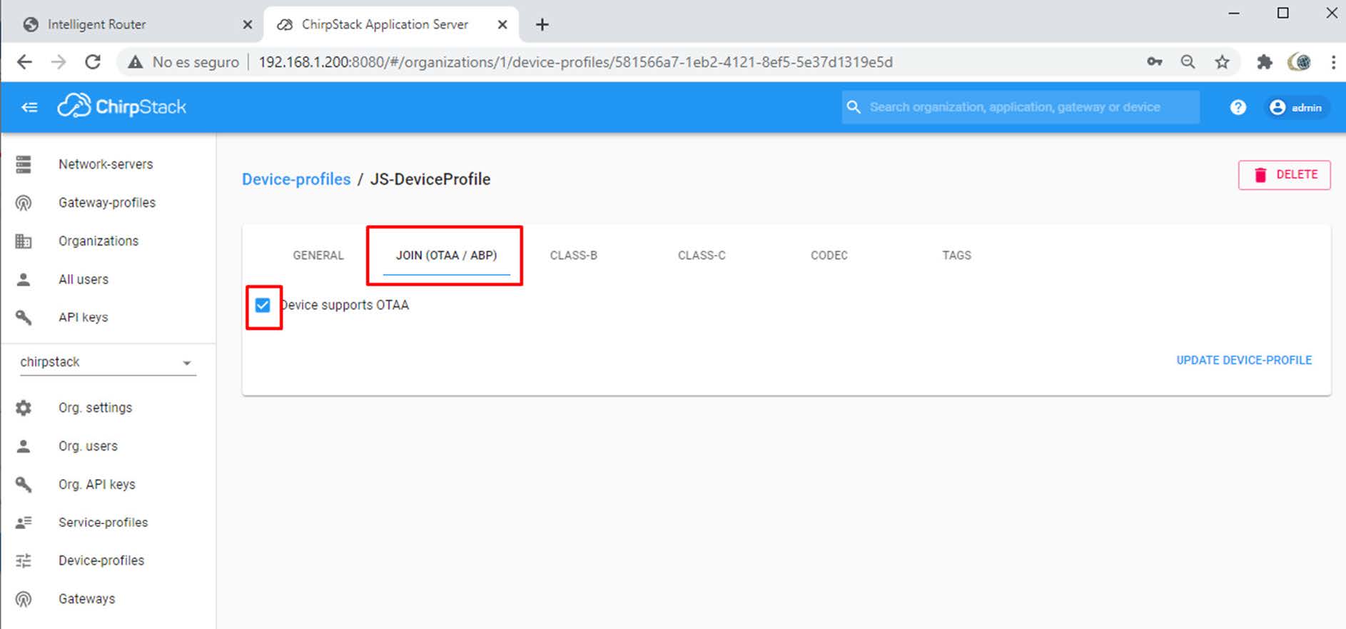
If you want to add external devices using OTAA pls check JOIN fields. If you will use ABP keys leave this box unmarked.

width=1886

In this example, we will use default DEVEUI and Lora Keys stored in the nodes (some explanation in Step 7)

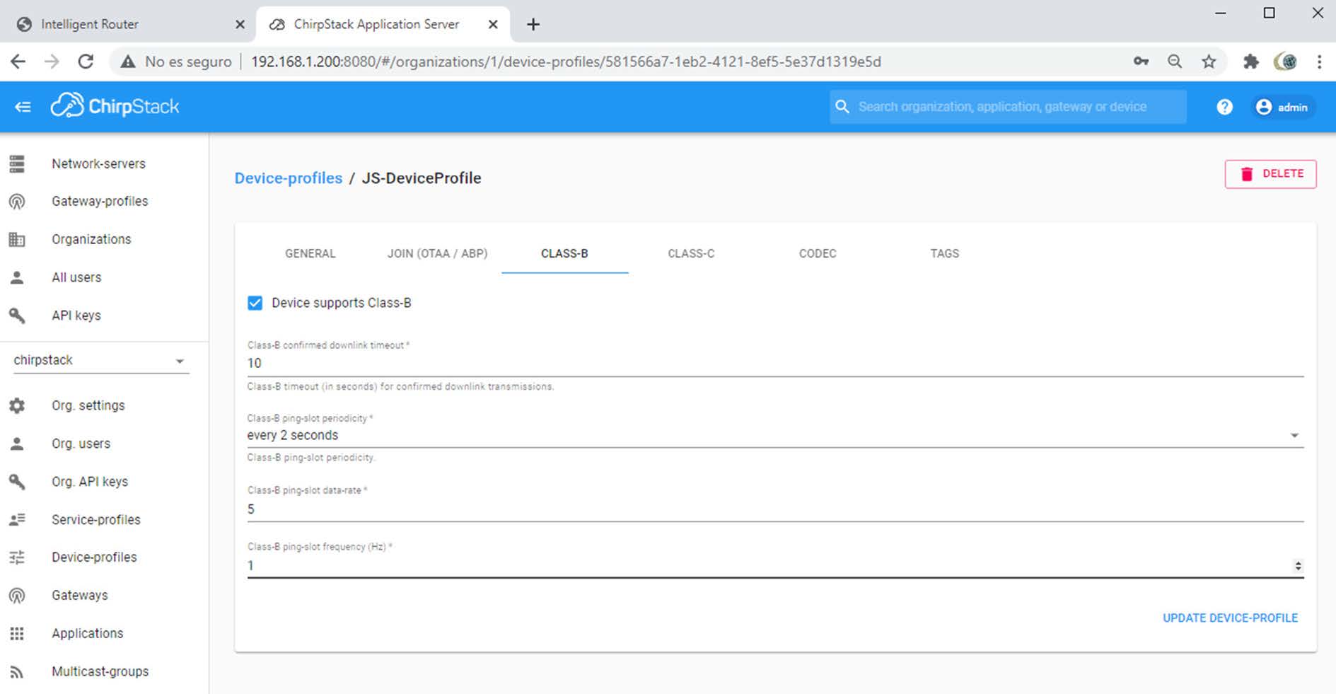
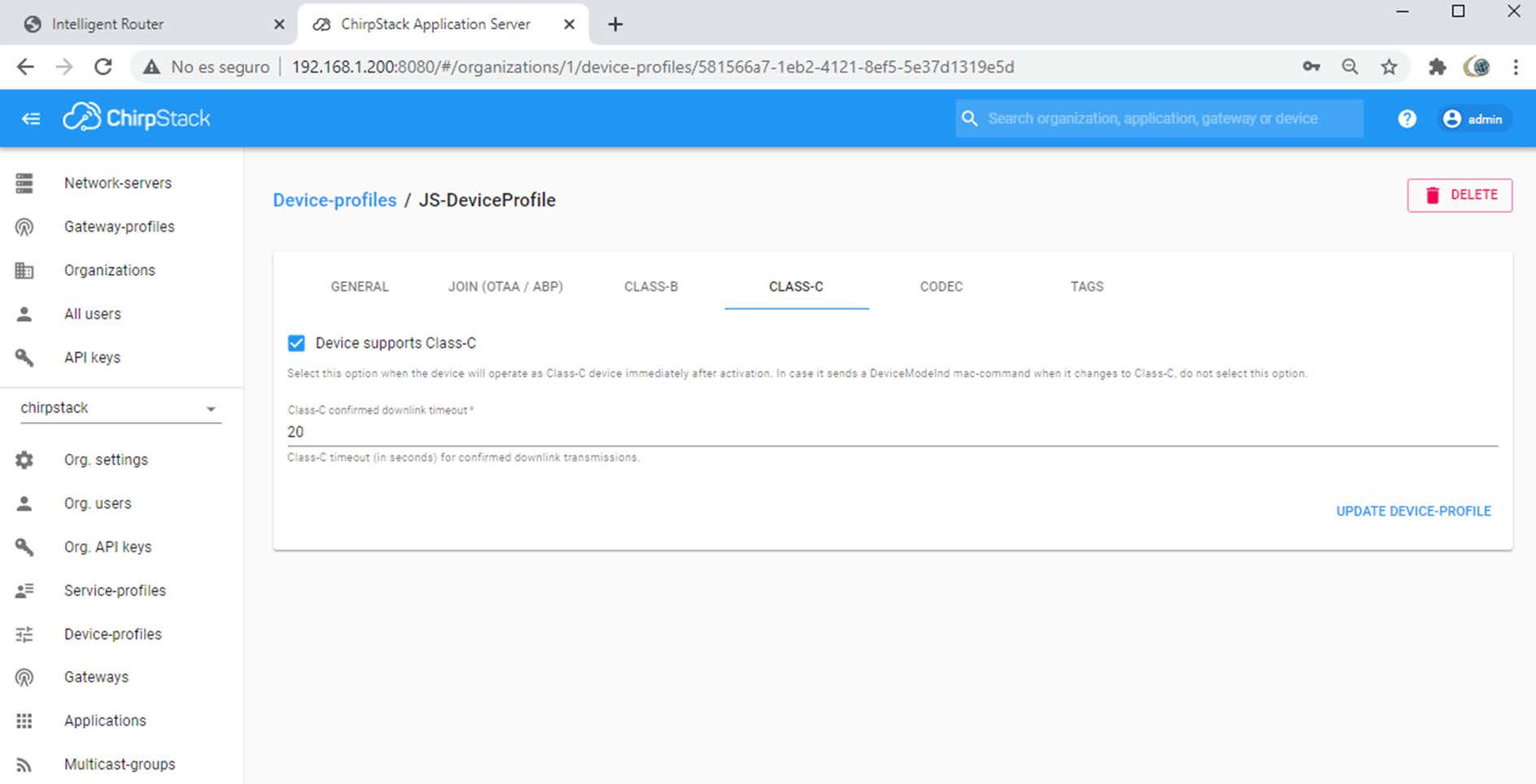
Fill CLASS-B and CLASS-C windows with YOUR specified LoRa scenario or adjust to your best performance features. This are some examples:

width=1889

width=1887

CODEC is a good ChirpStack feature. This is intented to get an object with extracted payload information and not all payload from the node.

If you are going to use just one type of same end LoRaWan sensors, you can ask your node manufacturer and fill/code. Read documentation/help. We will not use this feature in this application note.

width=1153

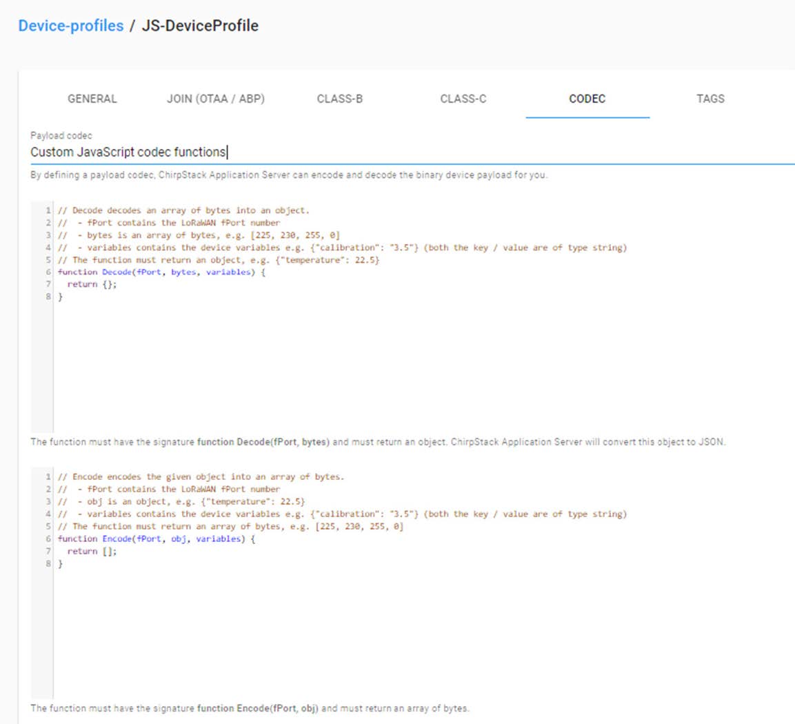
At the end of this application note you can see how we have CODEC code integrated in end IOT cloud Cervello.

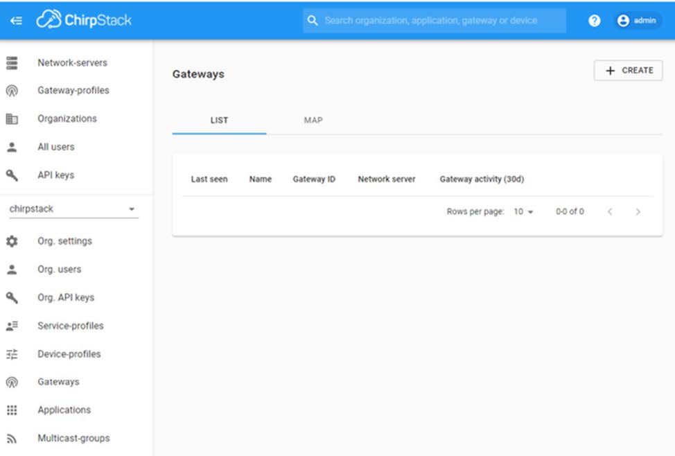
Step 5: Adding/Creating a Gateway

This section may be not important but it is, we have to add and create the MTX-StarLora as a Gateway. Click on Gateways:

width=974

Then click on Create.

width=1851

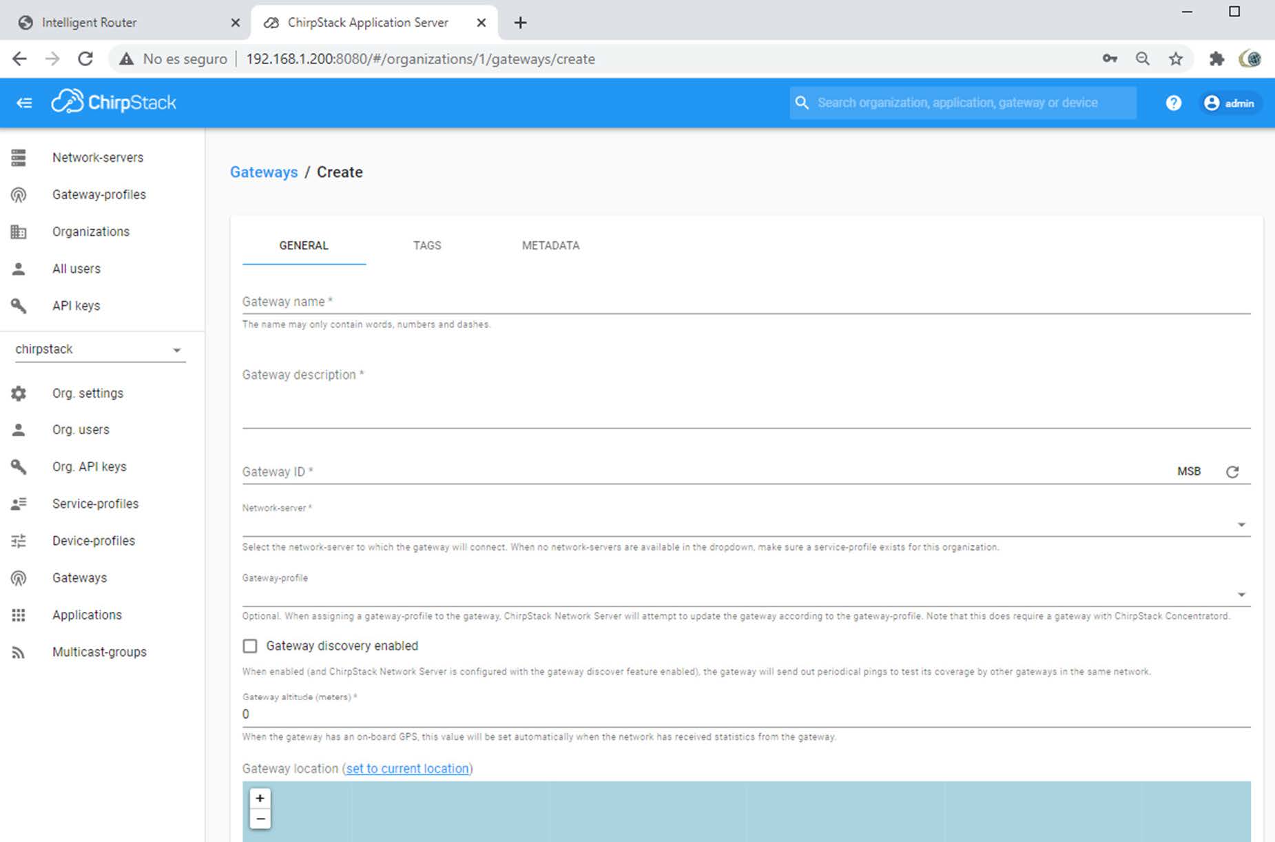
And write some name on Gateway name and some Gateway description string.

Also fill some Gateway ID (Identification), as example 010203040a0b0c0d

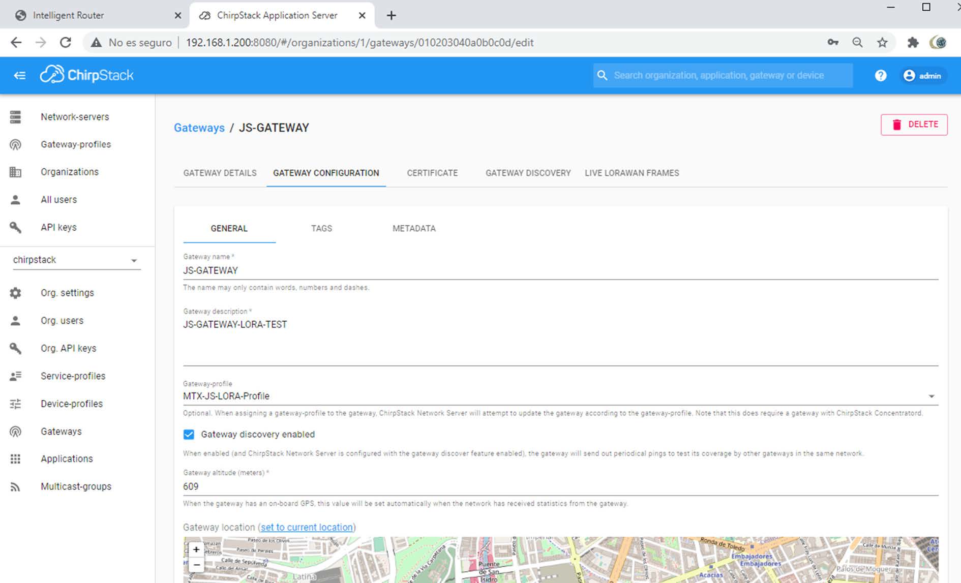
In this example, Gateway name is JS-GATEWAY. Has also to use the Gateway-profile set as step 2.

width=1890

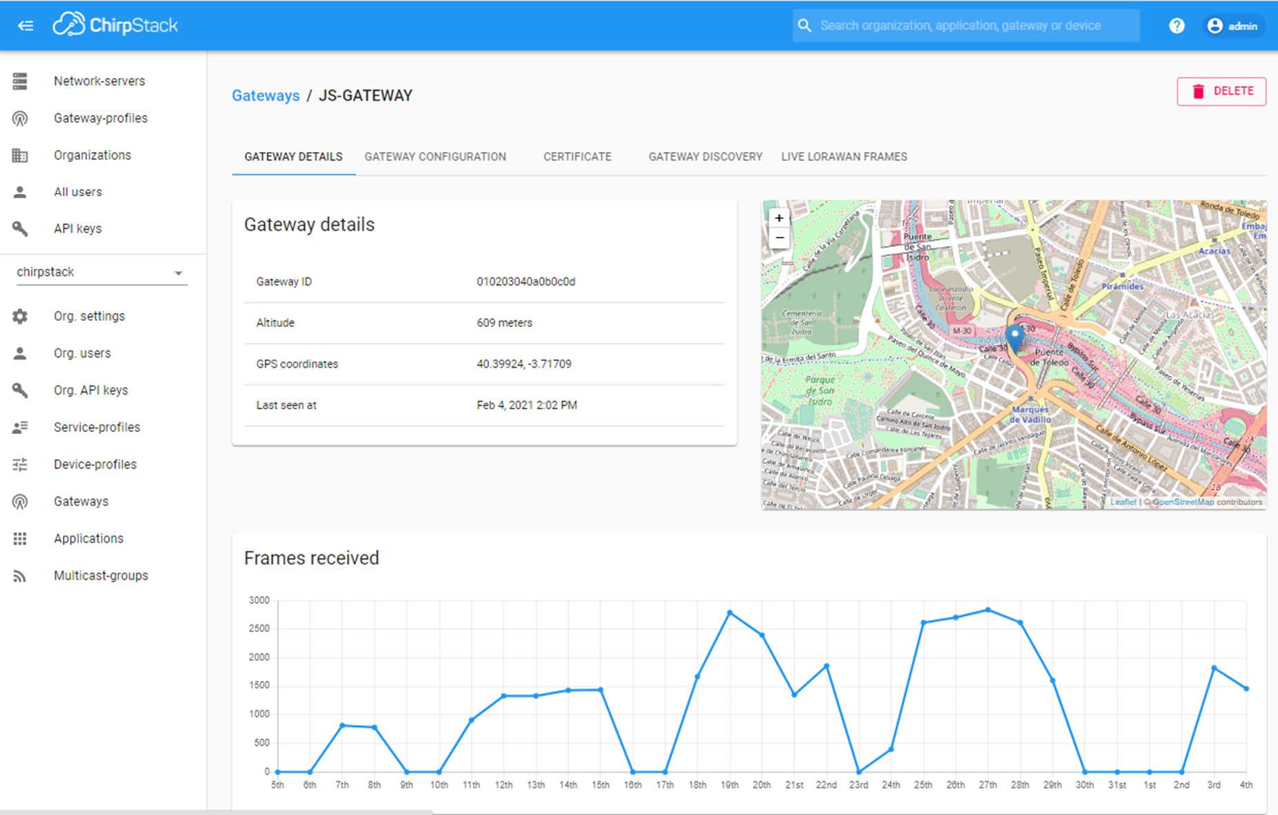
If successful you will get some live information:

width=1848

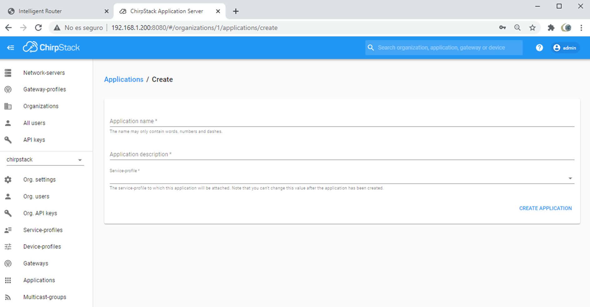
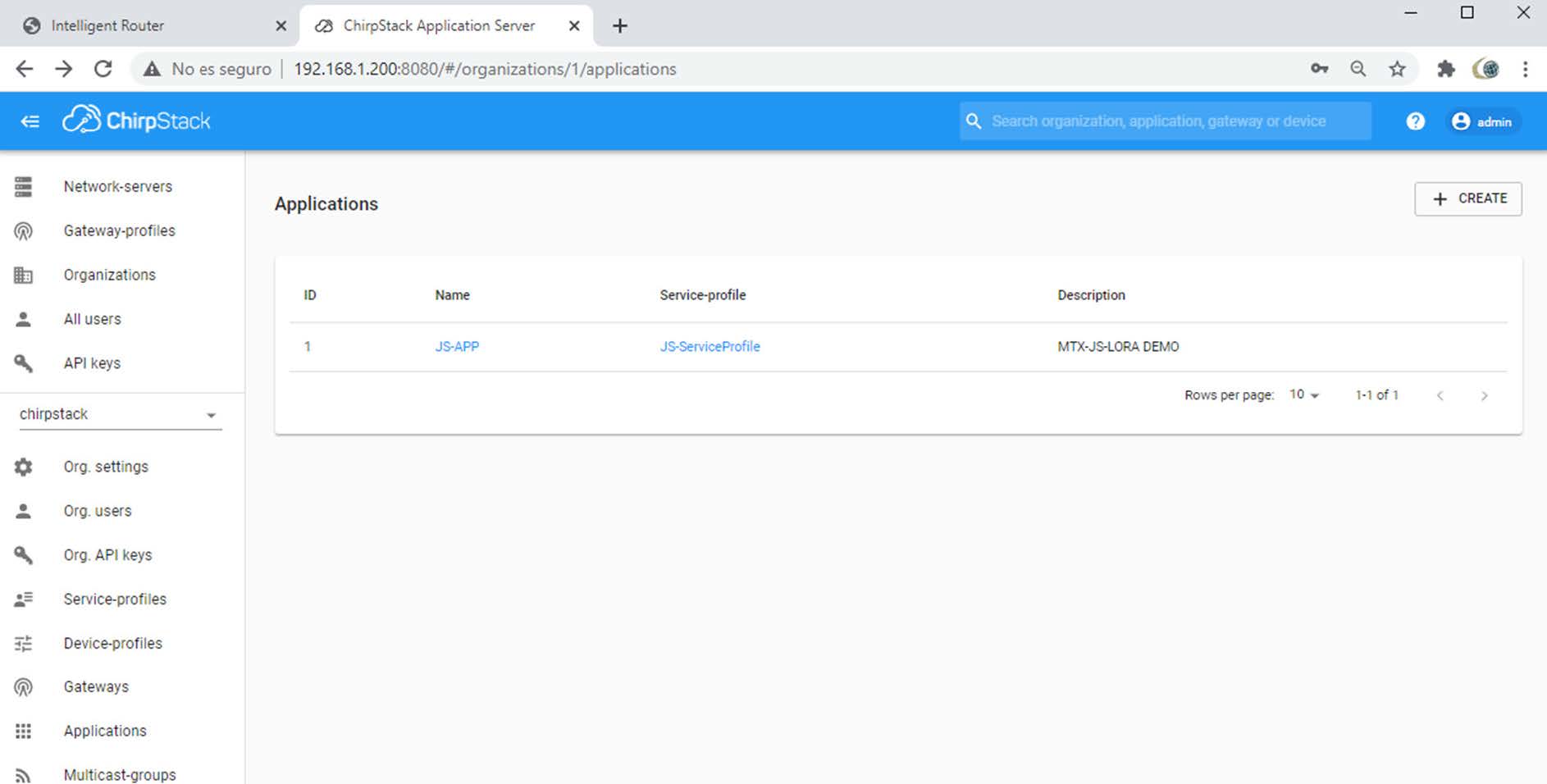
Step 6: Adding/Creating an Application

We are almost finishing, next point is creating a new Application. In this section we will also add the end LoRaWan nodes devices and see the payload.

Create an Application.

Click on Application -> Create

width=983

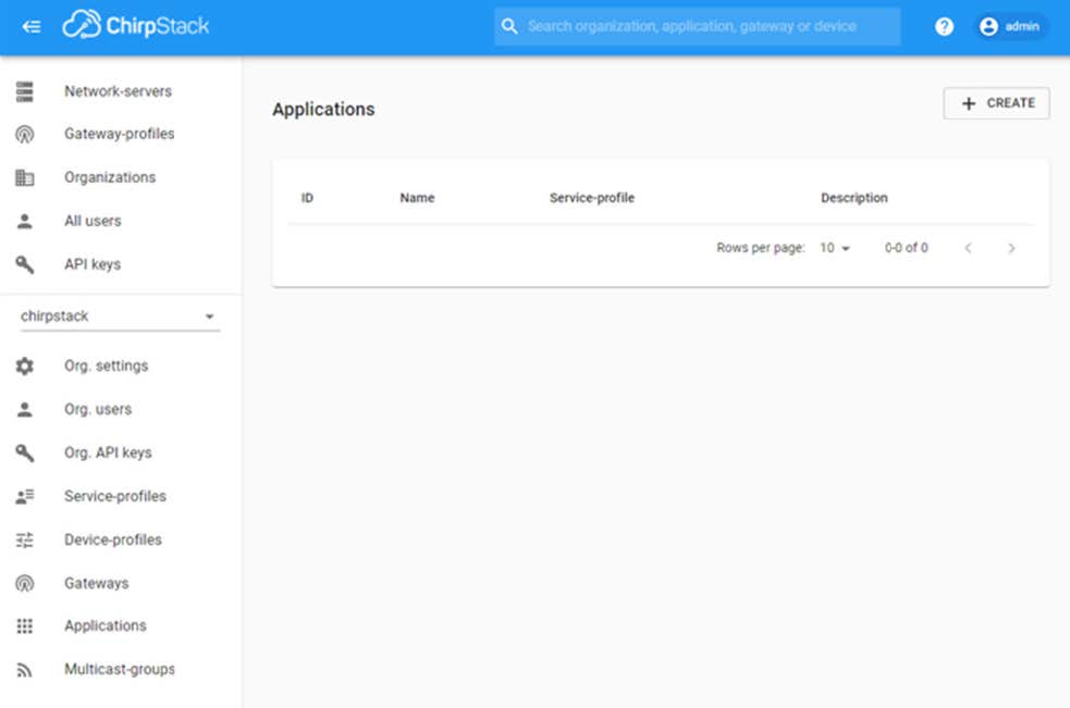
Fill Application name and Application description with some text strings and use Service Profile configured in step 3.

width=1888

As an example this is an application created.

width=1886

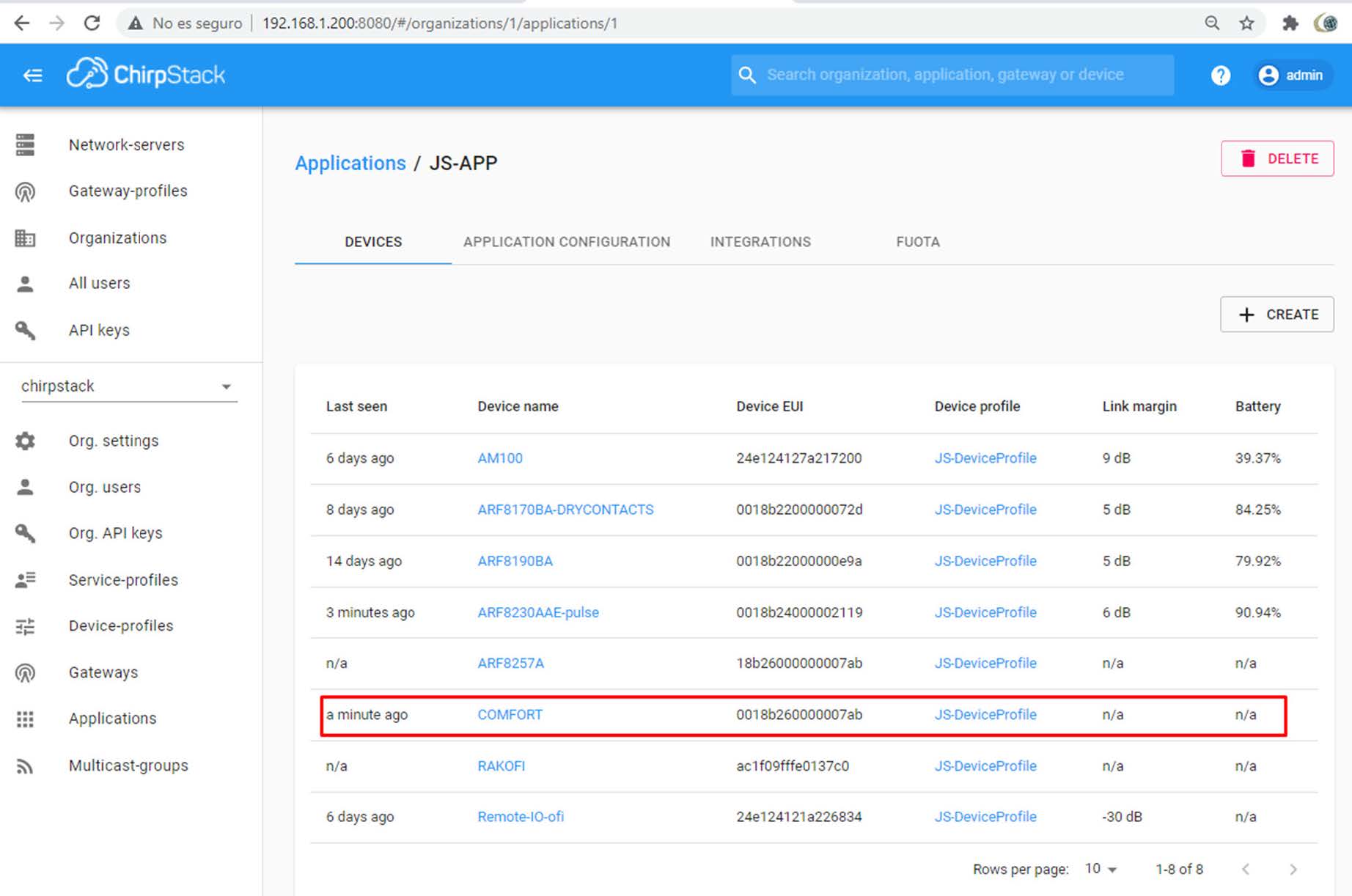
Step 7: Adding Devices

IMPORTANT POINT: Now we will create and add new end nodes LoRaWan devices.

width=1001

Take now the information of your LoRaWan device node.

You will need mandatory information:

  • DEVICE EUI (DEV EUI)
  • APPLICATION KEY (APP KEY)

You can get this information from your device provider, and sometimes, connecting the end remote device to your laptop.

HOW TO USE ADEUNIS END DEVICE
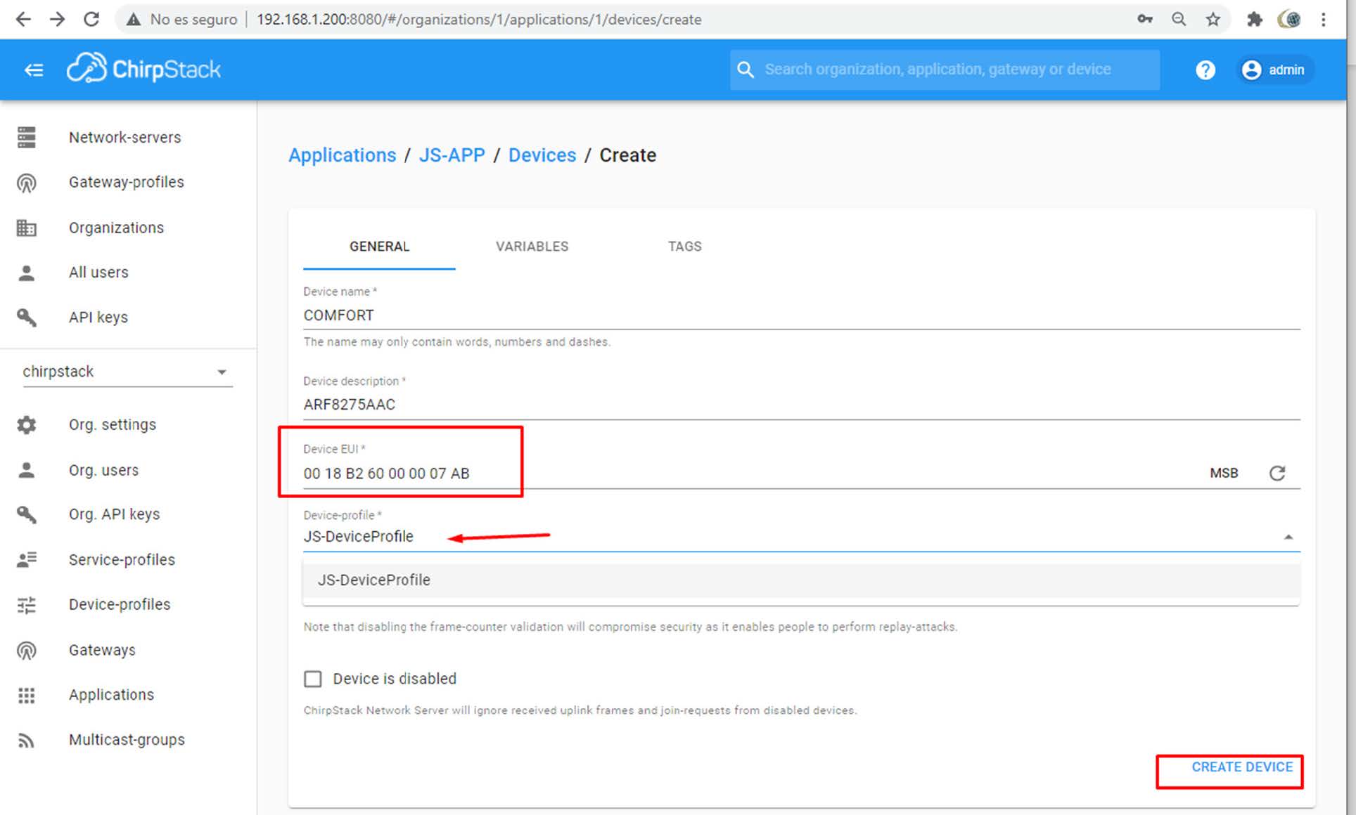
COMFORT ARF8275AAC

width=1594

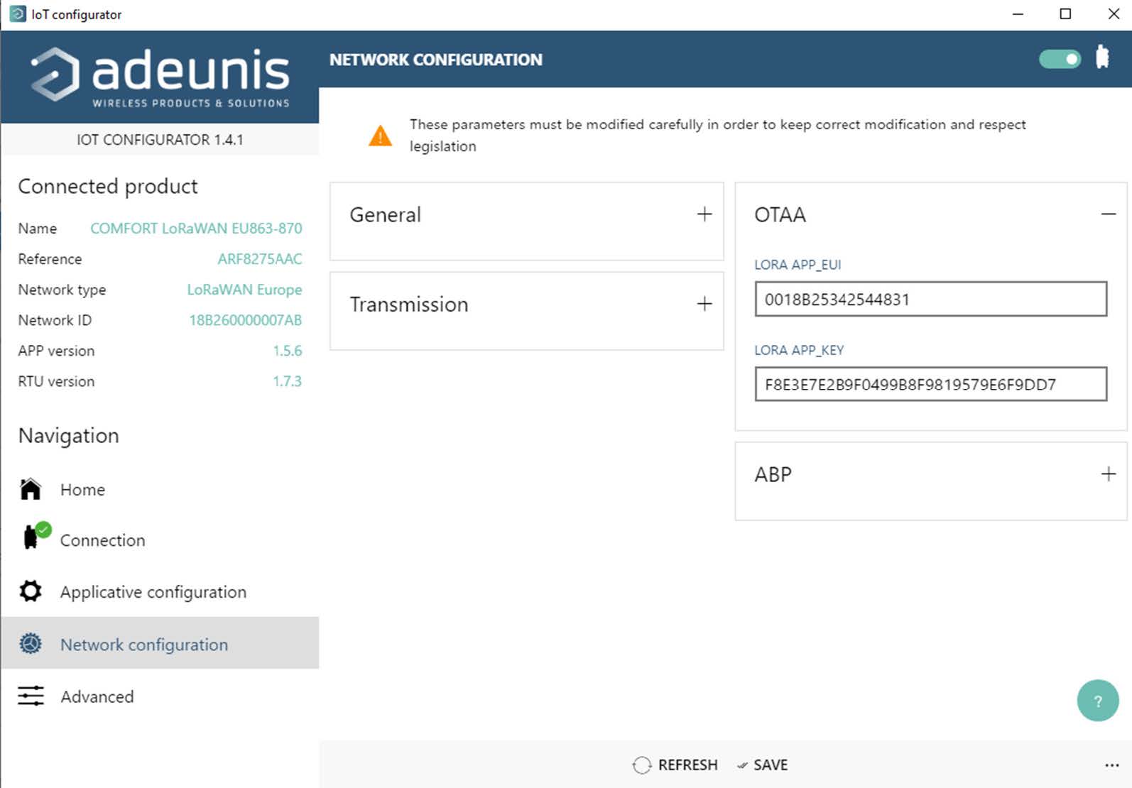
Here you can extract DEV EUI

18B260000007AB

Introduce this data into Device description. Fill with 00 at the beginning just in case.

width=1928

Goto into Devices/MyDevice:

width=1885

width=1602

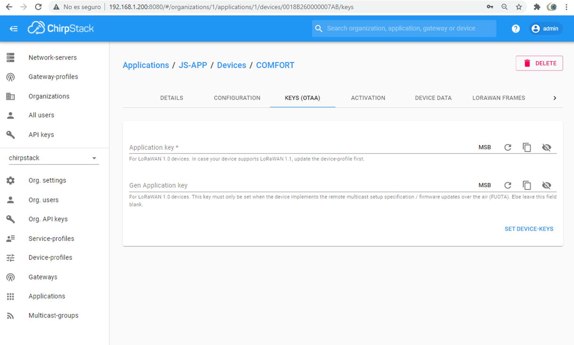
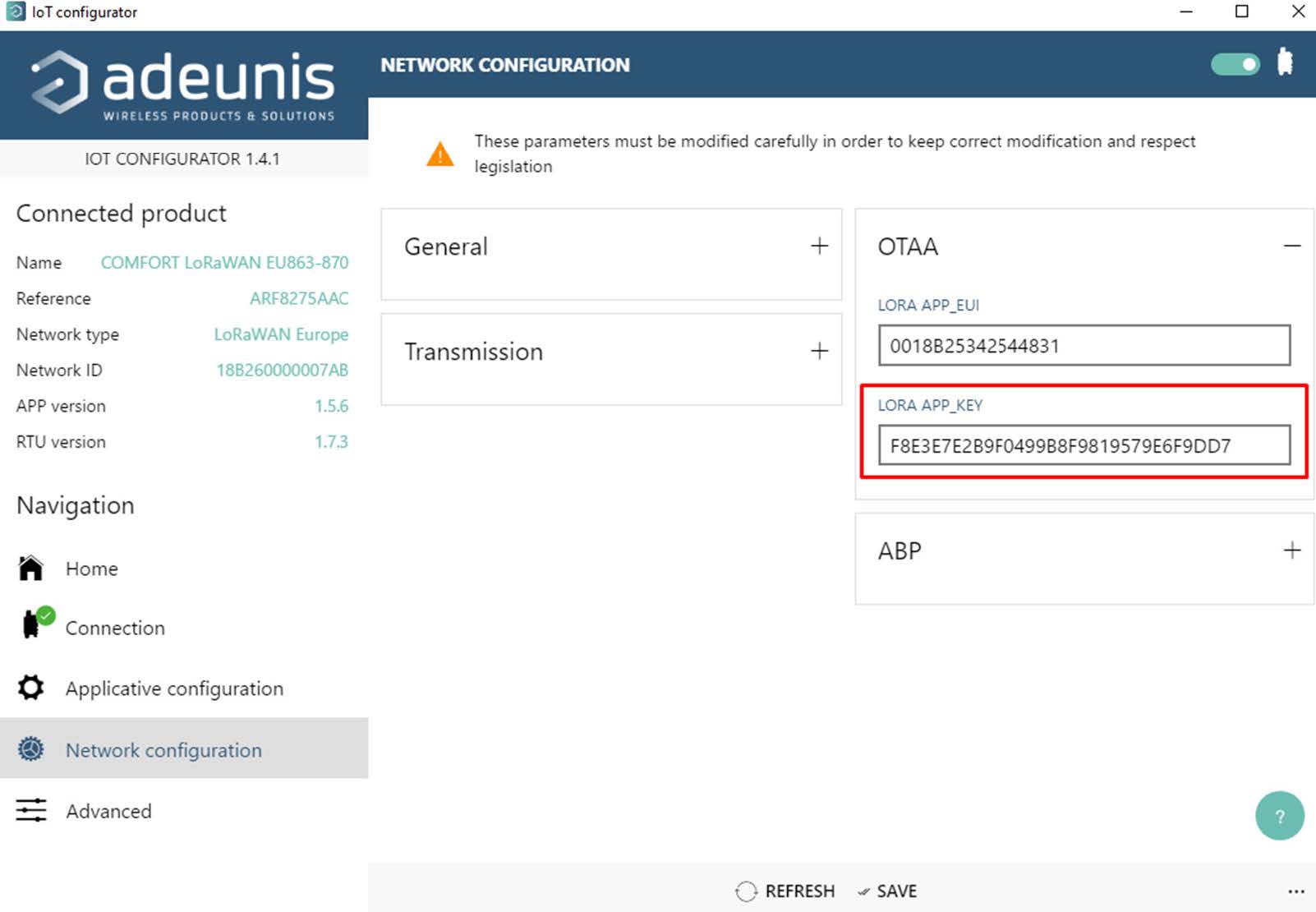
Copy the Lora App key.

width=1887

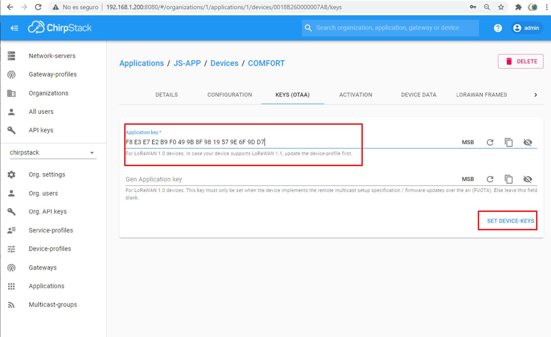
Keep Gen Application key in blank.

And then click on SET DEVICE KEYS.

width=1889

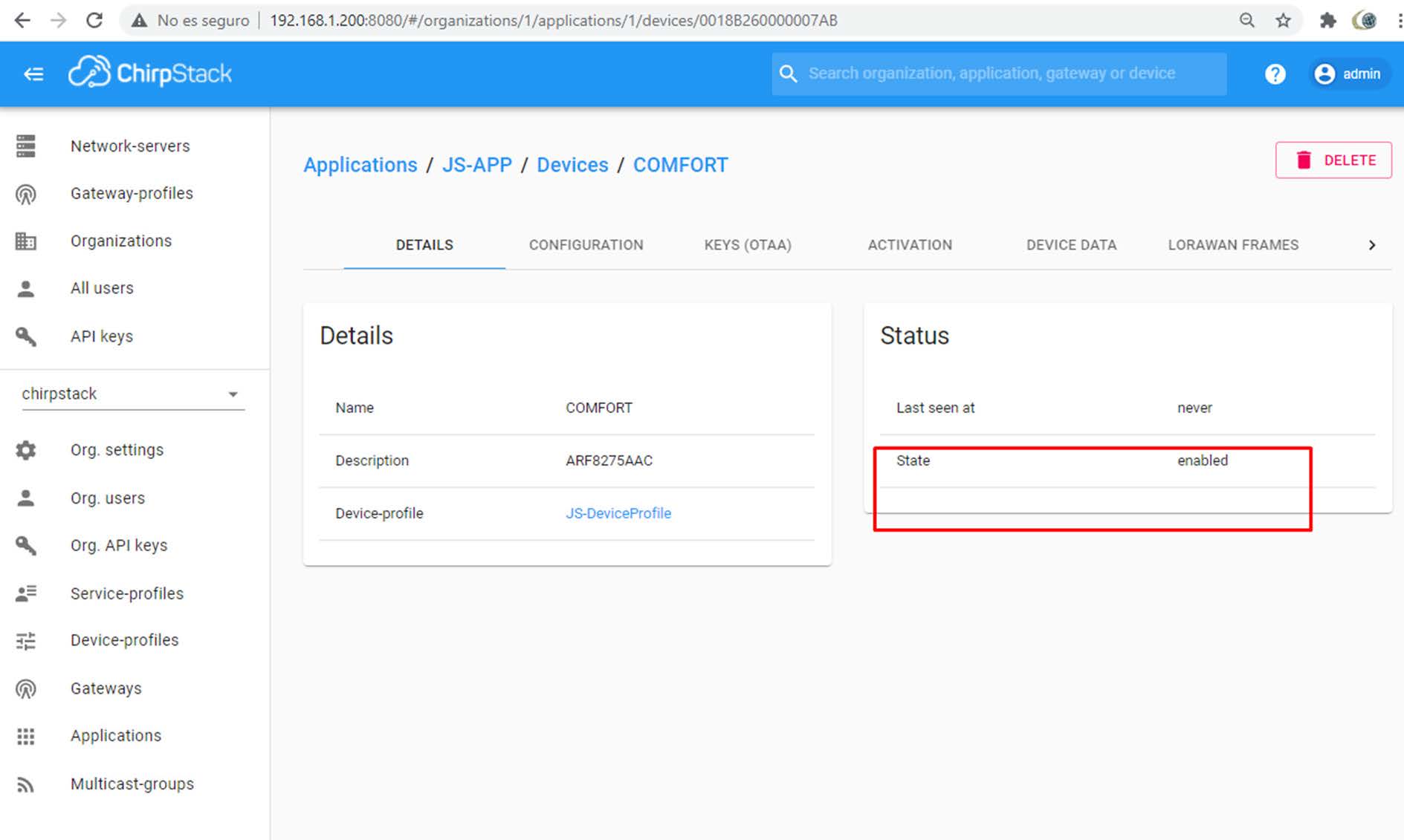
Wait till frames are received.

width=1844

width=1849

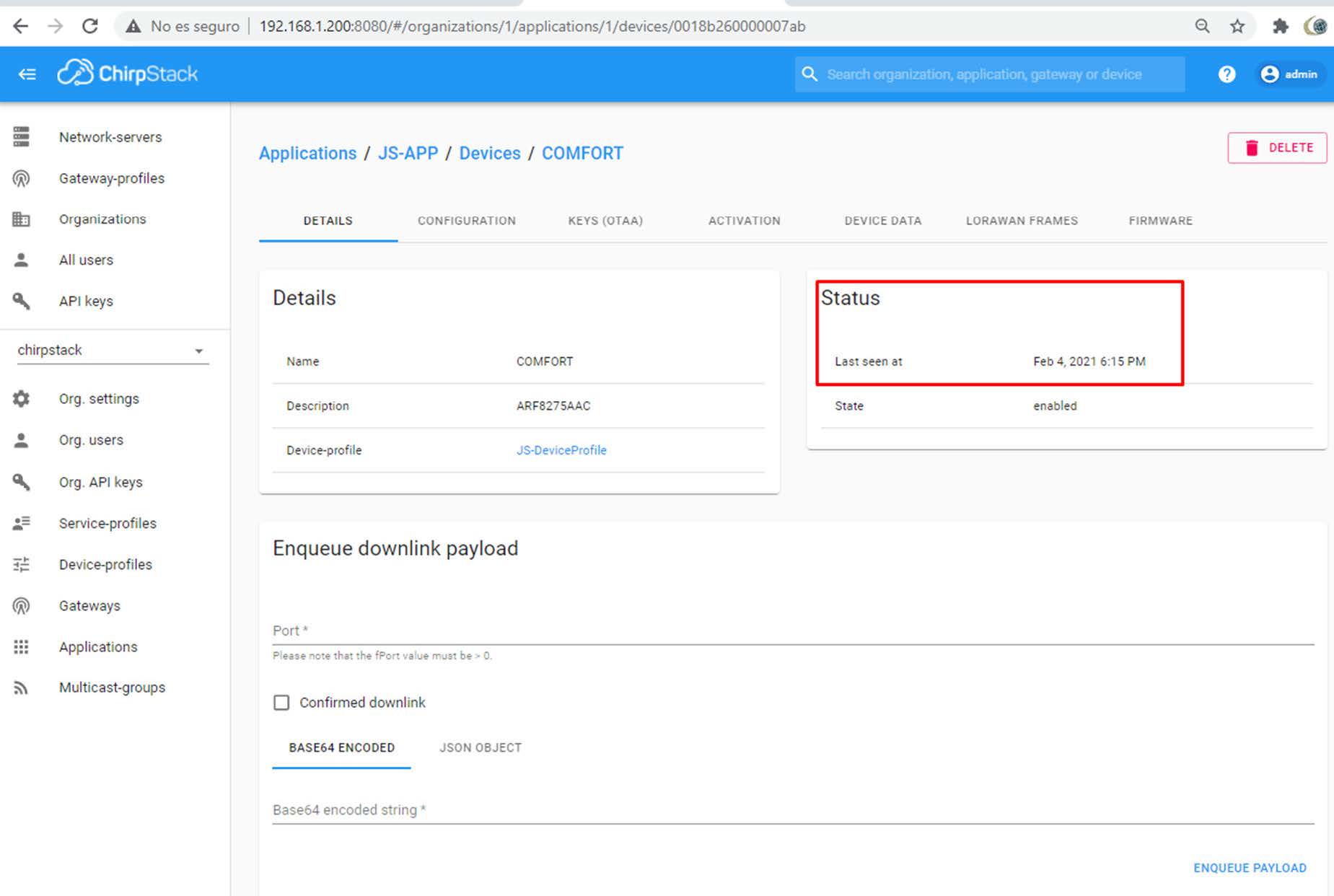
Click Device Data. Wait. Wait.

width=1531

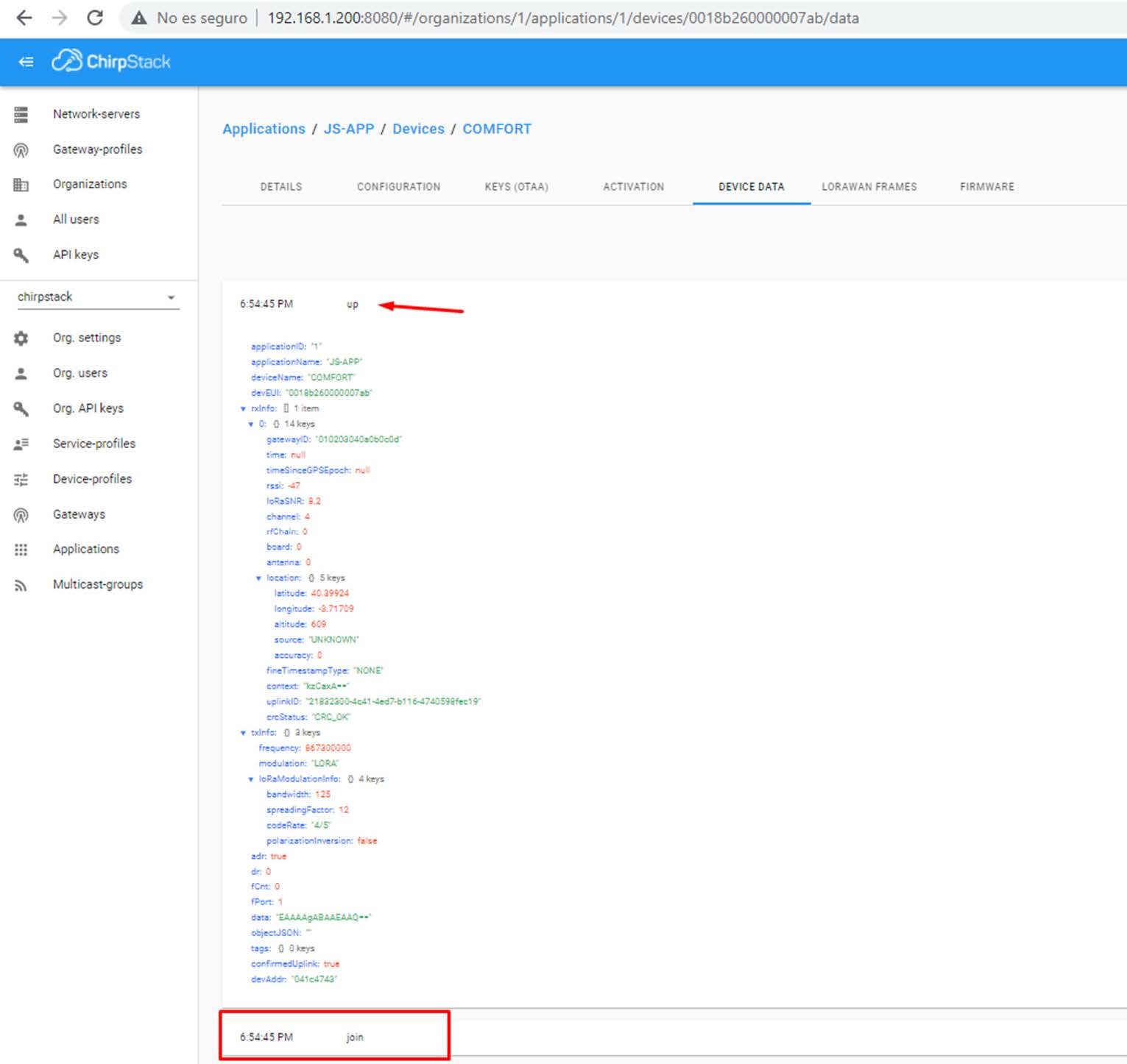
You will find some join and up messages. Click on up and extract.

width=280

adr:true

dr:0

fCnt:323

fPort:1

data:TIAA5Sc=

objectJSON:

Read the manual and extract the information from this string.

Data is Base64 have to decode to HEX. Use

https://cryptii.com/pipes/base64-to-hex

4c 80 00 e5 27 -> 4c8000e527

You can use Adeunis manual but use https://codec-adeunis.com/decoder

{
  type: 0x4c Comfort data,
  status: {
    frameCounter: 4,
    hardwareError: false,
    lowBattery: false,
    configurationDone: false,
    configurationInconsistency: false
  },
  decodingInfo: values: [t=0, t-1, t-2, ...],
  temperature: {
    unit: °C,
    values: [
      22.9
    ]
  },
  humidity: {
    unit: %,
    values: [
      39
    ]
  }
}

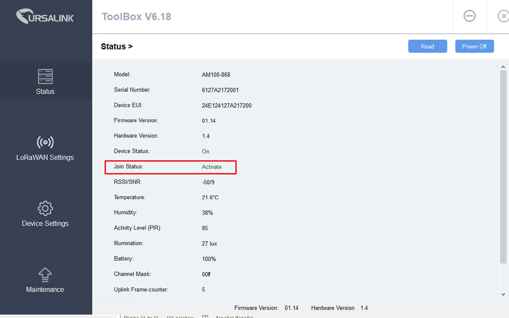
Another example with Ursalink device. Connect AM100 to computer using USB cable and open ToolBox.

width=1805

In this software you can find Device EUI. Rembember this number is like IMEI, MAC… stored in the device and normally, can not be changed. In this case, we will use Application Key generated randomly by ChirpStark and we will copy it to Ursalink.

width=1658

width=1807

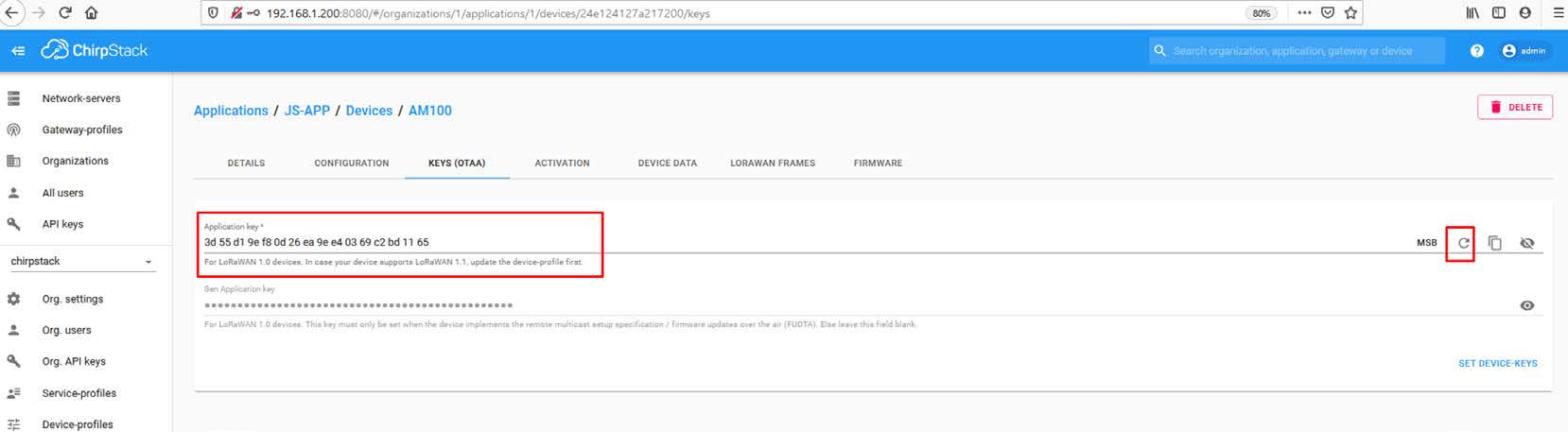
An important check on the device side is see if its Activaded.

width=1776

Check now again Devices traffic messages:

width=1516

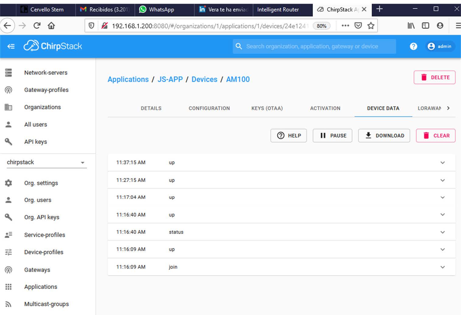
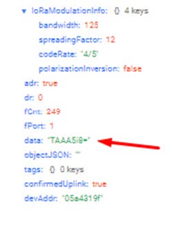
Click on up message, and again similar information structure, information about network, LoRa and the data.

data:A2fUAARoSQZlIgAbAAYABWoAAA== ???

UC11: • data:AWfZAAJoPw==

Remote io home • data:CQEA


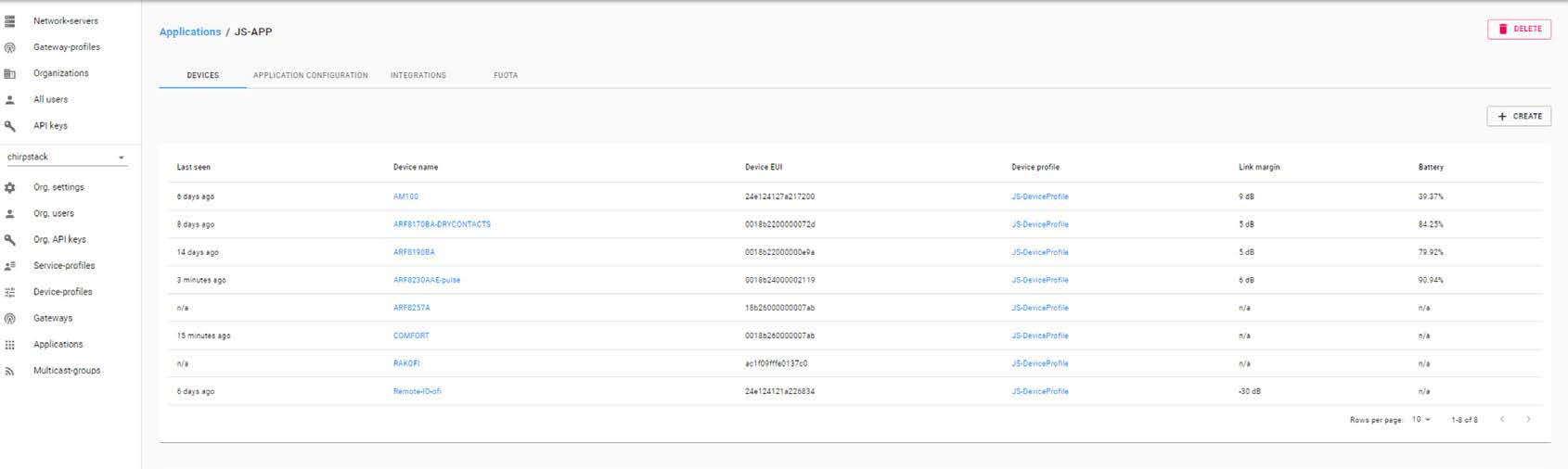
This sensor can read temperature, humidity and has a presence PIR. Adding more nodes will be like this:

width=1690

Keep in mind the LoRa frames, payloads are not getting out the ChirpStack server and/or be in Titan. Those are separate applications and we can not use any Titan information way (mqtt, http,,, etc). The only way to extract and send that information is, in Applications, use Integrations. Go to Applications>Integrations. You will find some integration with end cloud services:

HTTP

AWS SNS

AZURE

GCP

INFLUXDB

myDevices

SEMTECH

ThingBoards.io

We will use HTTP as maybe the easy way to POST all lora frame to a Server.
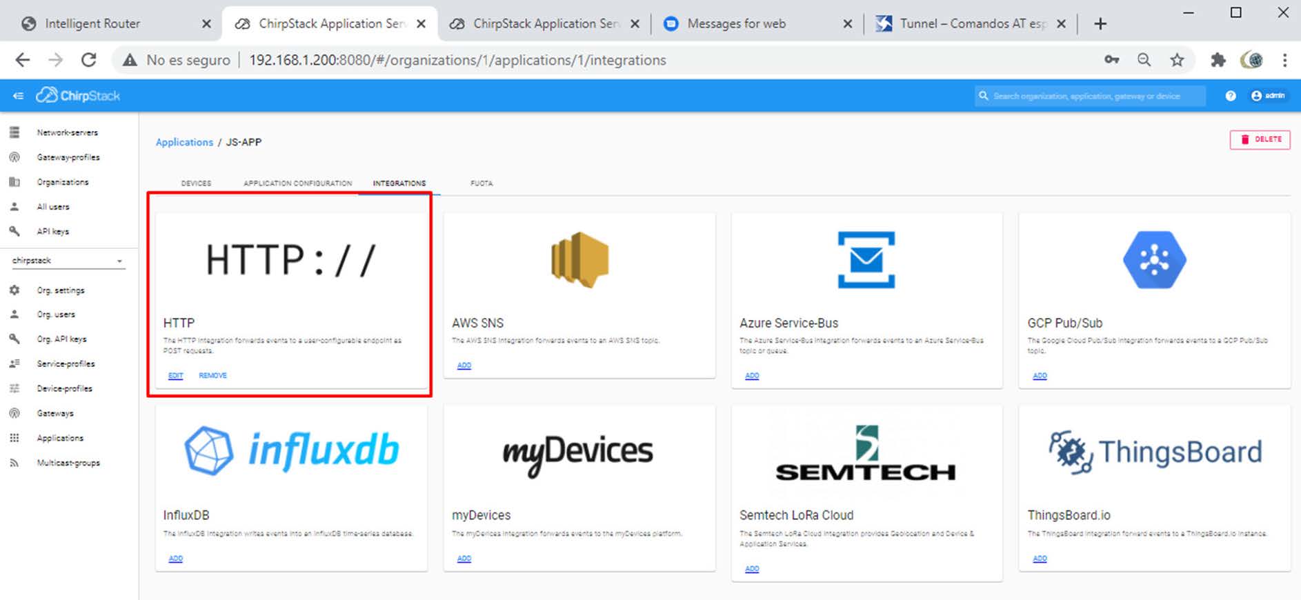
width=1886

Click on EDIT.

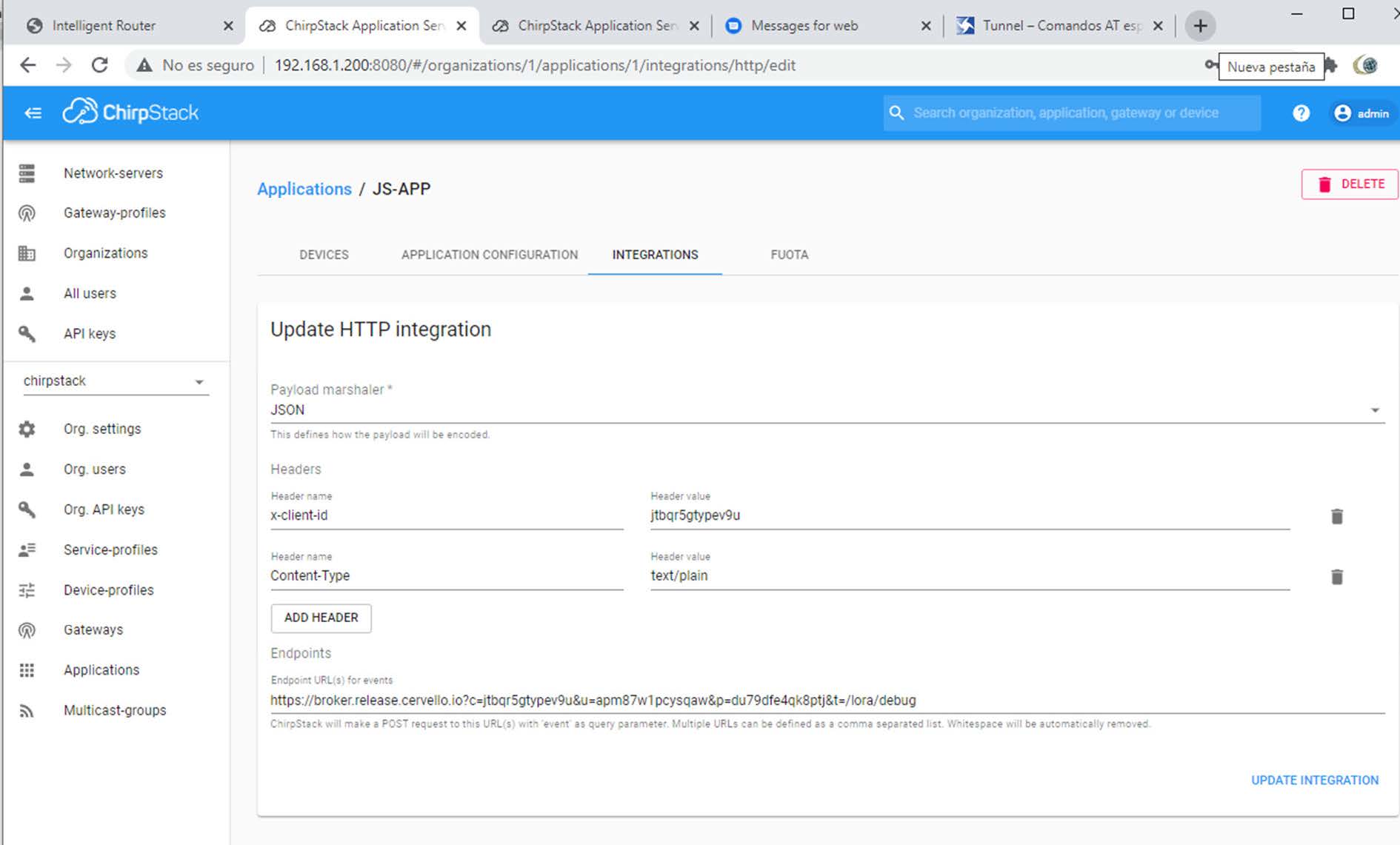
And fill the information.

In following example, we will use Cervello cloud platform to collect all the Lora payloads, decode and create simple Telemetries values.

Cervello collect information in a JSON payload (among other). Just adjust 2 headers and, the most important field is the URL.

In our case, we must fill in the URL the ID and password to connect properly to Cervello. You can also see we have created in Cervello a topic to receive these frames.

width=1890

HTTP Integration Using Cervello Stem

Create a NEW DEVICE (an already Organization created is needed, if not, create a new one).

Fill in name field some name, in our example, MTX-StarLora-STAR-LORA-TEST. Fill in Description some description, in our example, TEST LORA HTTP.

Device type: GATEWAY

Communication Protocol: DEFAULT

And Connectivity Media: Other

Then, Device Credentials are created.

Please keep attention. Click on Device Credentials.Then a box appears with

  • CLIENT ID
  • ACCESS KEY
  • ACCESS TOKEN

width=660

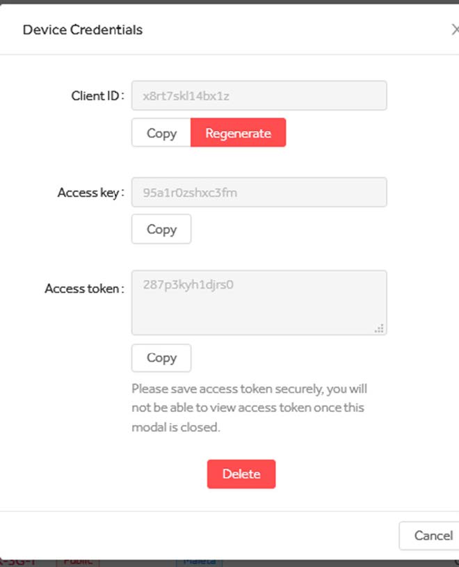
Copy them in some document as Access Token will not appear anymore. In our case,
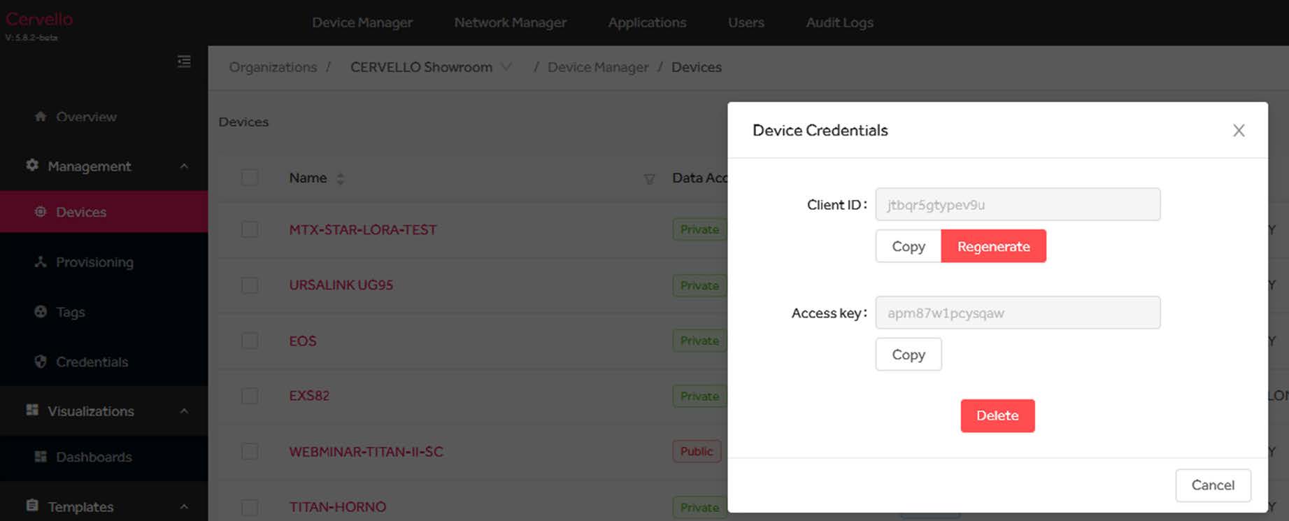
width=1843

We have:

  • Client ID: jtbqr5gtypev9u
  • Access key: apm87w1pcysqaw
  • Access tocken: du79dfe4qk8ptj

The URL in ChripStack is then:

https://broker.release.cervello.io?c=jtbqr5gtypev9u&u=apm87w1pcysqaw&p=du79dfe4qk8ptj&t=/lora/debug

In Cervello we will use VPI programming interface with the following steps:

  • Create an application (our example AppStarLora)
  • Link device to application

Create a VPI, in our case VPI-StarLora name.

Add following block:

Device Data Listener and write a name to Topic, in our example, lora/debug

width=1739

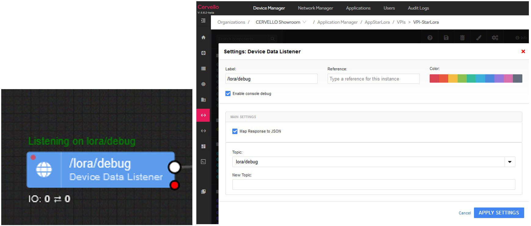
On debug you can see some live LoRa packet, this case is an Adeunis end node.

{
  organizationId: 1973cbd9-75a2-4599-aa90-6bae7f37a204,
  originatorId: b89dd4ed-9297-424b-8e18-020df9662c5d,
  deviceId: b89dd4ed-9297-424b-8e18-020df9662c5d,
  deviceName: MTX-StarLora-STAR-LORA-TEST,
  referenceName: null,
  applications: [
    82e3c562-48eb-4223-9056-21449b44f684
  ],
  assets: [],
  tags: [],
  customFields: null,
  isPublic: false,
  clientId: jtbqr5gtypev9u,
  topic: /lora/debug,
  payload: {
    applicationID: 1,
    applicationName: JS-APP,
    deviceName: COMFORT,
    devEUI: ABiyYAAAB6s=,
    rxInfo: [
      {
        gatewayID: AQIDBAoLDA0=,
        time: null,
        timeSinceGPSEpoch: null,
        rssi: -47,
        loRaSNR: 10.5,
        channel: 4,
        rfChain: 0,
        board: 0,
        antenna: 0,
        location: {
          latitude: 40.39924,
          longitude: -3.71709,
          altitude: 609,
          source: UNKNOWN,
          accuracy: 0
        },
        fineTimestampType: NONE,
        context: dUmrDA==,
        uplinkID: lhkyE2YbTg2sHkKG7C0krw==,
        crcStatus: CRC_OK
      }
    ],
    txInfo: {
      frequency: 867300000,
      modulation: LORA,
      loRaModulationInfo: {
        bandwidth: 125,
        spreadingFactor: 12,
        codeRate: 4/5,
        polarizationInversion: false
      }
    },
   adr: true,
    dr: 0,
    fCnt: 416,
    fPort: 1,
    data: TCAA5Cg=,
    objectJSON: ,
    tags: {},
    confirmedUplink: true,
    devAddr: BaQxnw==
  },
  time: 1612525208425,
  action: message_publish

This other is the URSALINK AM100.

{
  organizationId: 1973cbd9-75a2-4599-aa90-6bae7f37a204,
  originatorId: b89dd4ed-9297-424b-8e18-020df9662c5d,
  deviceId: b89dd4ed-9297-424b-8e18-020df9662c5d,
  deviceName: MTX-StarLora-STAR-LORA-TEST,
  referenceName: null,
  applications: [
    82e3c562-48eb-4223-9056-21449b44f684
  ],
  assets: [],
  tags: [],
  customFields: null,
  isPublic: false,
  clientId: jtbqr5gtypev9u,
  topic: /lora/debug,
  payload: {
    applicationID: 1,
    applicationName: JS-APP,
    deviceName: AM100,
    devEUI: JOEkEnohcgA=,
    rxInfo: [
      {
        gatewayID: AQIDBAoLDA0=,
        time: null,
        timeSinceGPSEpoch: null,
        rssi: -40,
        loRaSNR: 12.8,
        channel: 4,
        rfChain: 0,
        board: 0,
        antenna: 0,
        location: {
          latitude: 40.39924,
          longitude: -3.71709,
          altitude: 609,
          source: UNKNOWN,
          accuracy: 0
        },
        fineTimestampType: NONE,
        context: fhjurA==,
        uplinkID: q9xQmrwcQSadGQo+iSI2Tw==,
        crcStatus: CRC_OK
}
    ],
    txInfo: {
      frequency: 867300000,
      modulation: LORA,
      loRaModulationInfo: {
        bandwidth: 125,
        spreadingFactor: 10,
        codeRate: 4/5,
        polarizationInversion: false
      }
    },
    adr: true,
    dr: 2,
    fCnt: 3,
    fPort: 85,
    data: AXVkA2f1AARoUQZlFAAaAAkABWoAAANn9QAEaE8GZRQAGgAJAAVqAAA=,
    objectJSON: ,
    tags: {},
    confirmedUplink: true,
    devAddr: BfRdnw==
  },
  time: 1612525356533,
  action: message_publish
}

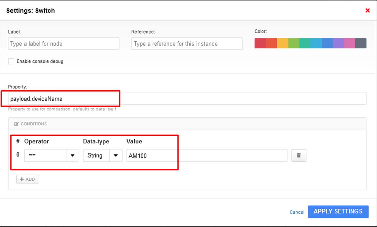
Our task now is filter the frames using ID, in our Switch block.

width=1326

width=1271

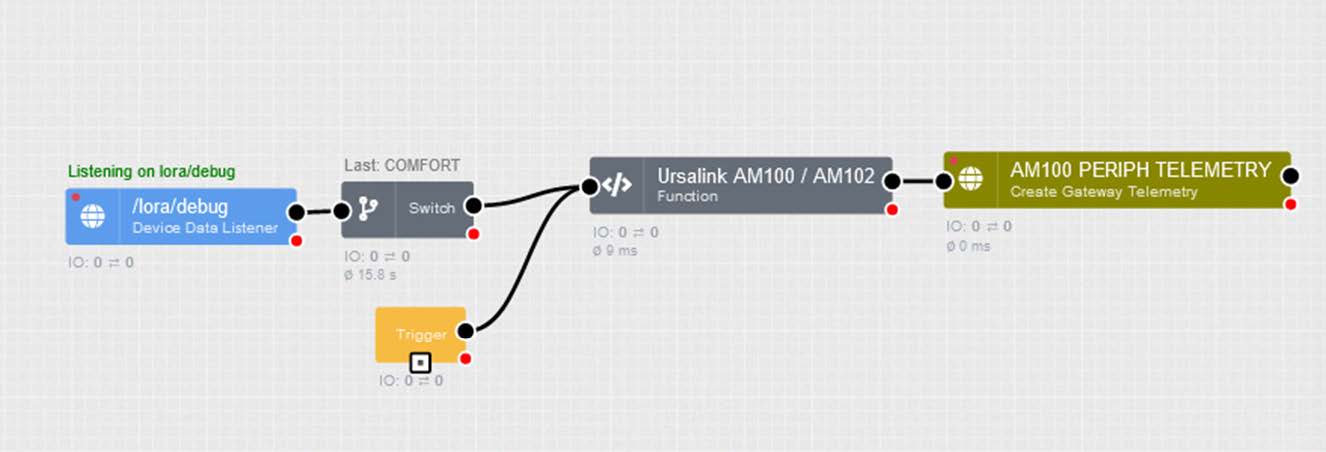
Function block is to decode the frame information. Ask your LoRaWan end device to get some information and example code. It is usually named CODEC.

/**
 * Ursalink AM100 / AM102 Payload Decoder
 *
 * definition [channel-id] [channel-type] [channel-data]
 *
 * 01: battery      -> 0x01 0x75 [1byte]  Unit: %
 * 03: temperature  -> 0x03 0x67 [2bytes] Unit: °C
 * 04: humidity     -> 0x04 0x68 [1byte]  Unit: %
 * 05: PIR          -> 0x05 0x6A [2bytes] 
 * 06: illumination -> 0x06 0x65 [6bytes] Unit: lux
 * ------------------------------------------ AM100
 * 07: CO2          -> 0x07 0x7D [2bytes] Unit: ppm
 * 08: TVOC         -> 0x08 0x7D [2bytes] Unit: ppb
 * 09: Pressure     -> 0x09 0x73 [2bytes] Unit: hPa
 * ------------------------------------------ AM102
 */
function Decoder(bytes) {
    var decoded = {};

    for (var i = 0; i < bytes.length;) {
        var channel_id = bytes[i++];
        var channel_type = bytes[i++];
        // BATTERY
        if (channel_id === 0x01 && channel_type === 0x75) {
            decoded.battery = bytes[i];
            i += 1;
        }
        // TEMPERATURE
        else if (channel_id === 0x03 && channel_type === 0x67) {
            decoded.temperature = readInt16LE(bytes.slice(i, i + 2)) / 10;
            i += 2;
        }
        // HUMIDITY
        else if (channel_id === 0x04 && channel_type === 0x68) {
            decoded.humidity = bytes[i] / 2;
            i += 1;
        }
        // PIR
        else if (channel_id === 0x05 && channel_type === 0x6A) {
            decoded.activity = readInt16LE(bytes.slice(i, i + 2));
            i += 2;
        }
        // LIGHT
        else if (channel_id === 0x06 && channel_type === 0x65) {
            decoded.illumination = readInt16LE(bytes.slice(i, i+2));
           // decoded.infrared_and_visible = readInt16LE(bytes.slice(i + 2, i + 4));
           // decoded.infrared = readInt16LE(bytes.slice(i + 4, i + 6));
            i += 6;
        }
        // CO2
        else if (channel_id === 0x07 && channel_type === 0x7D) {
            decoded.co2 = readInt16LE(bytes.slice(i, i + 2));
            i += 2;
        }
        // TVOC
        else if (channel_id === 0x08 && channel_type === 0x7D) {
            decoded.tvoc = readInt16LE(bytes.slice(i, i + 2));
            i += 2;
        }
        // PRESSURE
        else if (channel_id === 0x09 && channel_type === 0x73) {
            decoded.pressure = readInt16LE(bytes.slice(i, i + 2))/10;
            i += 2;
        } else {
            break;
        }
    }
    return decoded;
}

/* ******************************************
 * bytes to number
 ********************************************/
function readUInt16LE(bytes) {
    var value = (bytes[1] << 8) + bytes[0]; return value & 0xffff; } function readInt16LE(bytes) { var ref = readUInt16LE(bytes); return ref > 0x7fff ? ref - 0x10000 : ref;
}

/* ******************************************
 * payload processing
 ********************************************/

var hexBase64Payload = data.payload.data;

var hexPayload = Buffer.from(hexBase64Payload,\'base64\');
var decodedPayload = Decoder(Buffer.from(hexPayload,\'hex\'));


var msg = {
    device_name: data.payload.deviceName,
    deviceId: data.deviceId,
    data: {}
}

msg[data][data.payload.deviceName] = {
           data: decodedPayload }
    

send(0, msg);

Almost finished. In VPI, telemetry block create one TELEMETRY, in our example, will take just TEMP as a Telemetry value.

width=1149

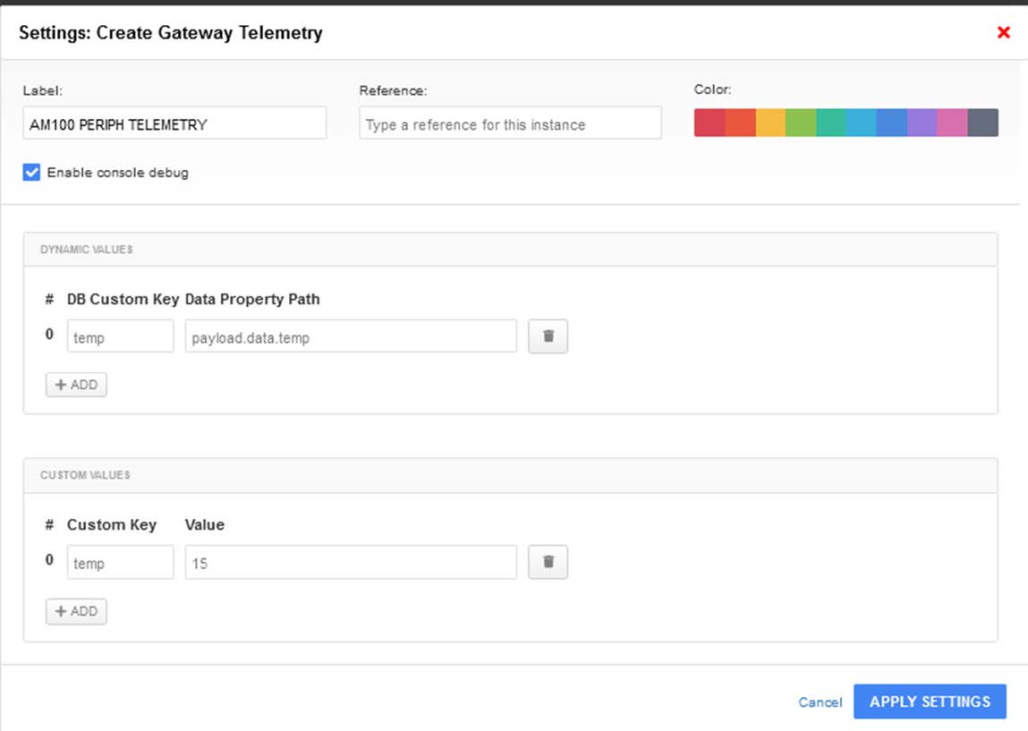
In this example, we have created a peripheral device which will allow separate telemetries and information from other nodes. This way will also do easy to create groups, tags, for a better end user experience.

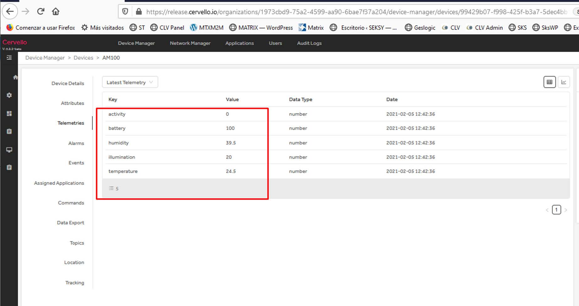
Clink on AM100 peripheral device in Device Manager and get all information.

width=1845

Do you have a question? Need a quote? Please contact us.

  • This field is for validation purposes and should be left unchanged.

Appendices and other documents

Annexes et autres documents

Appendices and other documents

Appendices and other documents

Appendices and other documents

Appendices and other documents

Appendices and other documents

Appendices and other documents

Appendices and other documents

FAQ

No, the concentrator is not able to decrypt data from WM-BUS equipment because it does not have a safe on board to guarantee the security of the encryption keys of your equipment. The recovered data is deposited without modification (without decryption) by the concentrator on your remote server.
Please check these items in this order:
  • the battery level: if the battery level is too low or empty, the product will not run properly or not run at all.
  • Modem reception level: a bad signal at the modem may also prevent the hub from uploading files. Look to move the product or install an external antenna to improve signal quality.
  • The last configuration file: a bad configuration file can block the product.

Remotely, by checking the regularly uploaded files if the product configuration is correct.

On site, by passing the magnet over the product, you will hear 3 short beeps.

Replace the product and inject the configuration from the old product into the new one. If a white list is used, remember to inject it into the new product as well.

Appendices and other documents

Other manuals

Application Notes

FAQ

Gateway configuration:

Start by checking that the computer’s IP parameters are compatible with the WebdynSunPM IP address (by default 192.168.1.12)

Launch a web browser (Chrome, Firefox, Edge, Safari, etc.) and enter the WebdynSunPM concentrator IP address in the address bar. An authentication page is displayed:

The default accesses are:

IdentifiantMot de passe
userhighhigh

Click “Login”

There are two configuration solutions, using the web interface and using text messages:
  • Configuration using the web interface:
Start by establishing a connection to the concentrator by connecting to it to access the server configuration: Enter the “ethernet” or “modem” connection type: For an ethernet configuration, make sure the IP parameters are compatible with server access according to the concentrator local network configuration. For an ethernet connection, the configuration must be compatible with the concentrator’s local network topology so that it can access the servers. This configuration is done from the “Networks” configuration page (see section 3.2.2.3: “Networks). For a modem connection, the modem configuration must be correct before a connection can be set up. This configuration is done from the “Modem” configuration page (see section 3.2.2.4: “Modem). The parameters for the servers to be configured are at least the following: Therefore the following fields need to be configured: “Interface”, “Type”, “Server type”, “Address”, “Port”, “Login” and “Password”. The other fields can be left at the default values subject to the directories having been properly created beforehand. See section 3.1.2: “Configuration files for more details.
  • Text message configuration:
Text message configuration requires sending the following commands:
      • Apn: to configure the SIM card APN. (see section 3.2:“apn” modem configuration command)
      • Ftp: to configure the FTP server that will contain the concentration configuration (see section 3.3: “ftp” FTP configuration command”).
      • Connect: to launch the connection to the FTP server and load the configuration (see section 3.1: ““connect” connection command

Access to the FTP server depends on the selected solution.

If you have chosen a portal, it will give you the FTP server access identifiers.

If you want to use your own FTP server, contact your network administrator.

For all other configurations, and to determine the best solution, contact the Webdyn sales department which will advise you and direct you to the relevant contacts: contact@webdyn.com

General gateway use

There are 2 methods to force a concentrator factory reset:
  • Press the Factory Reset button on the concentrator for 20 seconds:
Wait. The concentrator will reboot using its factory configuration.
  • If a SIM card is installed and configured, a “factory” text message can also be used for factory reset. Just send the “factory” text message to the SIM card phone number (see section 3.7: “factory” reset command”)

It is possible to send commands to connected devices if they accept them.

The WebdynSunPM can store up to 50Mb of uncompressed data per declared device.

If there is no access to the remote server, the WebdynSunPM concentrator can store the data for several months.

The maximum data storage time varies depending on the amount of data to be collected and the configured collection frequency.

The average storage time varies from 3 to 4 months.

The average service life of the battery is 5 years.

It may vary depending on the installation environment.

All our products are guaranteed for 2 years.

For more information, read the general terms and conditions of sale.

The data volume depends on the exchanged files.

The average is about 5 MB per month but this varies from one installation to another.

Inverter compatibility

See section 1.4: “Supported devices”.

Modbus device compatibility:

Yes, different Modbus devices can be connected to the same serial port.

Device compatibility:

    • Same type of RS485 or 4 wire connection.
    • All devices should be able to be configured using identical bus specifications. Same speed, same parity, same number of stop bits and data bits on all devices and on the WebdynSunPM.
    • Each device must be assigned a unique Modbus address (between 1 and 247) on the bus. (UnitID)

Appendices and other documents

FAQ

CONFIGURATION OF THE WEBDYNSUN GATEWAY

  • Start by checking that your computer’s IP parameters are compatible with the WebdynSun’s “IP” address (the default is 192.168.1.12). 
  • Next, launch a web browser (Firefox or IE) and enter the WebdynSun’s IP address in the address bar. An authentication page will appear: 

The default accesses are:
Username: userhigh
Password: high

  • Click on “log in”  

There are two types of configuration: via the web interface or via SMS.

Configuration of the web interface:

1/ Go to the configuration page with the gateway IP address (default 192.168.1.12)

2/ Go to the Configuration tab.

3/ Select either the Ethernet or modem connection mode:

If connecting via the local network (Ethernet):

  • Edit the WebdynSun’s IP parameters by assigning it a network-compatible address.

Please note, all fields must be completed in accordance with the configuration of your local network.

If connecting via the GPRS network (Modem):

  • Change the connection settings of the GPRS modem to the settings provided by your mobile operator.

4/ Edit the FTP server parameters.

5/ Confirm the changes.

6/ Restart the WebdynSun gateway using the new settings.

7/ In the menu, click on the “installation” tab, followed by the “connection” sub-tab and start the connection.

Configuration via SMS:

This configuration method requires the use of an active SIM card with a data option and a pin code that must be either “0000” or disabled.
The SIM card must be inserted into the unit before connection to the mains supply.
After connection to the mains supply, send the following SMS messages to the number of the previously inserted SIM card:

SMS for configuring the APN:
After replacing the generic fields with those of your operator, send the following SMS*:
apn=apn_name;usr=user_name;pwd=password;

Replace the above SMS fields with the following information:

  • apn_name: APN name supplied by your mobile operator
  • user_name: APN ID supplied by your mobile operator
  • password: APN password supplied by your mobile operator

SMS for FTP configuration:
After replacing the generic fields with those of your FTP server, send the following SMS*:
Ftp=server_name:user_name:password:port;

Replace the above SMS fields with the following information:

  • server_name: FTP server address
  • user_name: FTP account ID
  • Password: FTP account password
  • Port: FTP server port (the default port is 21)

Connection SMS:

Send the word “connect” by SMS* to launch a connection to the FTP server

*Please note: the formatting of the SMS must be exactly identical to that shown above (e.g.: no spaces between characters, etc.)

There are 2 ways of resetting the gateway.

  • If connecting by Ethernet:
    • Disconnect from the mains
    • Remove the cover
    • Disconnect the battery
    • Put the DIP Switch 2 on the WebdynSun card in “ON” position
    • Start the WebdynSun by connecting it only to the mains power supply
    • Wait until all the LEDs flash and then stop flashing (3 to 5 mins).
    • Disconnect from the mains
    • Reset the Dip Switch 2 to “OFF” 
    • Reconnect the battery
    • Reconnect to the mains supply and the WebdynSun starts normally.
  • If there is a SIM card inserted in the unit:
    • Send an SMS message containing the word “factory” to the number of the inserted SIM card.

NB : Resetting the gateway restores the configuration to its original state. Please note: data will be saved but the specific settings will not. Therefore, all the settings must be reconfigured.

Commands can be sent to connected devices with the exception of certain inverters and Modbus slaves that do not accept write requests.

If the device allows it, command files can be created on the FTP server.

The WebdynSun has a memory of about 100MB.

Therefore, if the remote server cannot be accessed, the WebdynSun gateway can backup data for several months.
The maximum data backup time varies depending on the amount of data to be collected.

The average backup time ranges from 3 to 4 months.

The average battery life is 5 years.

It may vary depending on the installation environment.

Yes, data may be sent to a PLC if the latter is equipped with a Modbus protocol.
The “Report” configuration file allows the WebdynSun gateway to automatically write the values read on a Modbus slave

All our products are guaranteed for 2 years.

For further information, please see our general conditions of sale.

Files uploaded by the WebdynSun gateway are compressed in Gz format.

The data contained in these files is structured in csv format.

The data volume depends on the files exchanged.

The average is about 5 MB per month but this varies from one installation to another.

INVERTER COMPATIBILITY WITH THE WEBDYNSUN GATEWAY

Different brands of inverter may be connected to the RS485(B) port or via the Ethernet port if the inverter protocol is based on the Modbus protocol (RTU or TCP).

However, different brands of inverters cannot be connected to the same RS485(A) port.

For a list of compatible inverters, please see the product page of the WebdynSun data gateway
  • Check if the correct inverter protocol is selected before starting detection:
  • Check the wiring and configuration of the inverters by referring to the inverter appendices.
  • Check that the inverters are not in OFF or stand-by mode.
  • Check that the line end plugs on the RS 485(A) Bus are turned on.

COMPATIBILITY WITH MODBUS DEVICES

Yes, any device you wish to connect must be configured and its Modbus definition file must be created.

The configuration is mainly based on the RS485 serial bus parameters and the IP parameters.

Yes, different Modbus devices can be connected to the same RS485 (B) port.

However, they must have the same communication parameters (bus parameters or compatible IP parameters), in order for them to communicate with each other.

Appendices and other documents

Appendices and other documents

Appendices and other documents

Appendices and other documents

Appendices and other documents

  • Warning – Firmware update V4.07.02 For the old version with SIM CARD of the pin code is 0000 you can update in this version. For the second case : When you insert a SIM CARD with pin code is 0000 used in this version (4.07.02) Downgrading to a previous version is not permitted.

Appendices and other documents

  • Warning – Firmware update V4.07.02 – For the old version with SIM CARD of the pin code is 0000 you can update in this version.

    For the second case : When you insert a SIM CARD with pin code is 0000 used in this version (4.07.02) Downgrading to a previous version is not permitted.

Annexes and other documents

FAQ

Annexes and other documents

FAQ

Annexes and other documents

FAQ

Annexes and other documents

FAQ

CONFIGURATION OF THE WEBDYNRF GATEWAY

  • If the file is deleted from the directory after connecting the WebdynRF gateway, the problem is usually due to a file format error. The configuration and control files must follow the format described in the schema (XSD) files. To check schema consistency, open the XML file with the Notepad++ text editor and install the “XML Tool” add-on. Next, copy the corresponding XSD file to the XML file in the same directory, and select “Validate now” in XML Tool. Errors detected by the tool should be displayed.
  • If the file is not deleted from the server, the most common problem is that the file has not been located correctly. The file must be available on the server in the “INBOX” directory and in the sub-directory bearing the product UID name (e.g.: “/INBOX/0045CE/”).

GENERAL USE OF THE WEBDYNRF GATEWAY

The amount of data exchanged on the GPRS network varies depending on the configuration. However, the average consumption would be about 5MB / month.
The WebdynRF gateway consumes an average of about 250mA.

There are 2 firmware updating methods:
Local updating:
On the WebdynRF configuration interface, go to the “Actions” tab and select the updater in the “File upload” menu before clicking on the “Upload” button

Remote updating:
Upload the file containing the updater (file with extension “.bz2”) in the “BIN” directory to the FTP server . Next, place the update command in the INBOX directory corresponding to your gateway (“INBOX/”, with, the identifier of the gateway concerned)

The update command must follow the following format:

      updater.tar.bz2
      checksum_md5

updater.tar.bz2
checksum_md5

With:

  • updater.tar.bz2: Updater file name uploaded to the “BIN” directory
  • checksum_md5: Md5 code of the updater file

A lack of connection to the FTP server may be due to a network connection problem (Ethernet or GPRS), an FTP login problem or a failure to initiate the connection.

If you cannot connect to the network, check the following points:

  • Ethernet:
    • Modem set to “off” or “always off”
    • “Gateway” fields correctly entered
    • At least one DNS server must be configured
  • GPRS:
    • Modem set to “on”
    • APN, APN ID and APN password correctly entered
    • GPRS call number set to “*99***1#”

If you cannot log in, check the following points:

  • Incorrect FTP parameters
  • TCP port 21 closed at output
  • Domain name resolution problem: the DNS server is not specified

If the connection fails to initiate:

In this case, only the automatic connection does not work. The problem is probably caused by an incorrect schedule configuration. Please note, the schedule ID must be an integer.

 PARTICULAR APPLICATION OF THE WEBDYNRF WIRELESS M-BUS GATEWAY

For the WM-bus module data to be transmitted, you must:

  • Choose the mode corresponding to the modules used (S, T or N)
  • Define the modules or groups of modules to be processed

A module may be defined in a unique way by all the fields below:

  • Id
  • Manufacturer
  • Version
  • Medium

If a module’s data is encrypted, the encryption key for this module can be defined in the “Key” field.

To simplify the entry of the modules to be processed, a module group can be defined that conforms to the fields entered. The other fields will then be left empty (below is an example of a configuration for retrieving all Webdyn manufacturer (WDN) modules with the encryption key “00000000000000000000000000000000”.

  •   Id :
  •   Manufacturer : WDN
  •   Medium :
  •   Version :
  •   Label : Webdyn
  •   Key : 00000000000000000000000000000000

Note: In order for the modules (filters) entered to be taken into account, the “ByPass filter” mode must be deactivated.

Click here to read the media file 

Click here to read the units file 

 PARTICULAR APPLICATION OF THE WEBDYNRF WAVENIS

The tool is connected to the gateway via the installer access (install).

It is therefore necessary to use the installer password (default is “middle”), and not the administrator’s password (default is “high”)

The statuses transmitted by the WebdynRF gateway are the raw values contained in the Wavenis modules. They are transmitted without interpretation. For further details, please refer to the Coronis module manuals.

Appendix and other documents

FAQ

CONFIGURATION OF THE WEBDYNRF GATEWAY

  • If the file is deleted from the directory after connecting the WebdynRF gateway, the problem is usually due to a file format error. The configuration and control files must follow the format described in the schema (XSD) files. To check schema consistency, open the XML file with the Notepad++ text editor and install the “XML Tool” add-on. Next, copy the corresponding XSD file to the XML file in the same directory, and select “Validate now” in XML Tool. Errors detected by the tool should be displayed.
  • If the file is not deleted from the server, the most common problem is that the file has not been located correctly. The file must be available on the server in the “INBOX” directory and in the sub-directory bearing the product UID name (e.g.: “/INBOX/0045CE/”).

GENERAL USE OF THE WEBDYNRF GATEWAY

The amount of data exchanged on the GPRS network varies depending on the configuration. However, the average consumption would be about 5MB / month.
The WebdynRF gateway consumes an average of about 250mA.

There are 2 firmware updating methods:
Local updating:
On the WebdynRF configuration interface, go to the “Actions” tab and select the updater in the “File upload” menu before clicking on the “Upload” button

Remote updating:
Upload the file containing the updater (file with extension “.bz2”) in the “BIN” directory to the FTP server . Next, place the update command in the INBOX directory corresponding to your gateway (“INBOX/”, with, the identifier of the gateway concerned)

The update command must follow the following format:

      updater.tar.bz2
      checksum_md5

updater.tar.bz2
checksum_md5

With:

  • updater.tar.bz2: Updater file name uploaded to the “BIN” directory
  • checksum_md5: Md5 code of the updater file

A lack of connection to the FTP server may be due to a network connection problem (Ethernet or GPRS), an FTP login problem or a failure to initiate the connection.

If you cannot connect to the network, check the following points:

  • Ethernet:
    • Modem set to “off” or “always off”
    • “Gateway” fields correctly entered
    • At least one DNS server must be configured
  • GPRS:
    • Modem set to “on”
    • APN, APN ID and APN password correctly entered
    • GPRS call number set to “*99***1#”

If you cannot log in, check the following points:

  • Incorrect FTP parameters
  • TCP port 21 closed at output
  • Domain name resolution problem: the DNS server is not specified

If the connection fails to initiate:

In this case, only the automatic connection does not work. The problem is probably caused by an incorrect schedule configuration. Please note, the schedule ID must be an integer.

 PARTICULAR APPLICATION OF THE WEBDYNRF WIRELESS M-BUS GATEWAY

For the WM-bus module data to be transmitted, you must:

  • Choose the mode corresponding to the modules used (S, T or N)
  • Define the modules or groups of modules to be processed

A module may be defined in a unique way by all the fields below:

  • Id
  • Manufacturer
  • Version
  • Medium

If a module’s data is encrypted, the encryption key for this module can be defined in the “Key” field.

To simplify the entry of the modules to be processed, a module group can be defined that conforms to the fields entered. The other fields will then be left empty (below is an example of a configuration for retrieving all Webdyn manufacturer (WDN) modules with the encryption key “00000000000000000000000000000000”.

  •   Id :
  •   Manufacturer : WDN
  •   Medium :
  •   Version :
  •   Label : Webdyn
  •   Key : 00000000000000000000000000000000

Note: In order for the modules (filters) entered to be taken into account, the “ByPass filter” mode must be deactivated.

Click here to read the media file 

Click here to read the units file 

 PARTICULAR APPLICATION OF THE WEBDYNRF WAVENIS

The tool is connected to the gateway via the installer access (install).

It is therefore necessary to use the installer password (default is “middle”), and not the administrator’s password (default is “high”)

The statuses transmitted by the WebdynRF gateway are the raw values contained in the Wavenis modules. They are transmitted without interpretation. For further details, please refer to the Coronis module manuals.

Annexes et autres documents

  • WARNING :  Pour les anciens produits qui disposent d’une carte SIM avec un code PIN à 0000 , la mise à jour vers la version 4.07.02 sera fonctionelle.

    Second cas : Si la carte SIM avec un code PIN à 0000 est utilisée dans cette version (4.07.02), le passage vers une mise à jour antérieure est interdit.