Suchen Sie etwas anderes?
Scenario details:
- We have 5 electric meters with ModBus RTU protocol. These meters have a series of readings in their internal memory (e.g. cumulative consumption and average consumption) which should be read and sent to a Web server periodically
- Therefore every 15 minutes the MTX-Tunnel has to question the 5 meters to read the records via a serial port. The records to be read are for the cumulative consumption (record nº20) and for average consumption (record nº 21)
- After every reading MTX tunnel has to send the records to a web server via HTTP GET using a JSON object. However it must be able to store up to 1500 readings in flash memory in case there is a communication failure with the 2G/3G/4G so that it can send them when the connection is restored. For each meter, it will send a JSON frame where it indicates the Modbus address/ identifier of the meter that has been read
- You need to be able to access MTX-Tunnel at any moment to be able to read PLC records in real time as well as being able to write them and modify the PLC configuration records
Solution: MTX-Tunnel firmware + MTX-Java-IoT/MTX-Java-T/MTX-Java-T2

Config.txt configuration file:
| Configuration | Observations |
| COMM2_baudrate: 9600 COMM2_bitsperchar: 8 COMM2_autorts: off COMM2_autorts: off COMM2_stopbits: 1 COMM2_parity: none GPRS_apn: movistar.es GPRS_login: MOVISTAR GPRS_password: MOVISTAR GPRS_timeout: 0 MTX_PIN: 0000 MTX_mode: none MTX_model: MTX-4G-JAVA-IOT-STD-N MTX_portAux: modbusmaster MTX_TPProtocol: ntp MTX_TPServer: ntp.roa.es MTX_TPServer2: es.pool.ntp.org MTX_ping: 35 MTX_pingIP: 8.8.8.8 SMS_allPhones: on SMS_sendIP: on SMS_ATEnabled: on SMS_ATResponse: on FIREWALL_enabled: off TELNET_enabled: on TELNET_login: user TELNET_password: 1234 TELNET_firewall: off LOGGER_enabled: on LOGGER_password: ID00001 LOGGER_server: www.miservidorWeb.com/json.asp?data= LOGGER_registerSize: 300 LOGGER_numRegistersFlash: 1500 LOGGER_httpMode: getjson MODBUS_address: 1;2;3;4;5 MODBUS_start: 20 MODBUS_numwords: 4 MODBUS_readCommand: 3 MODBUS_period: 900 |
Serial port (where internal GPS is connected) rate Number of bits No flow control No flow control 1 stop bit No parity APN GPRS from your network operator GPRS Login GPRS Password Modem is always GPRS connected SIM Card PIN MTX-Tunnel mode MTX modem model AUXILIAR COM port used as master modbus Time synch. protocol Time server Backup time server Ping every 35 minutes without comms IP address to ping All phone numbers are authorized IP sent to phone which called or “on” SM Remote AT commands by SMS enabled Modem response to AT command with SMS Any IP will be able to connect to the modem Telnet is activated Telnet login Telnet password Telnet port 20023 We enable the MTX Logger, to store the records Password field can be used as ID device Server URL, will receive JSON data Register size Maximum number of records in MTX HTTP GET (JSON) mode ModBus equipment address ModBus register address to be read Number of registers read Reading command Timing -seconds- read is repeated |
Details:
- The summary of this example is as follows: The modem will periodically read, every 15 minutes, two ModBus records from each counter and they will be sent to a web server via a JSON object (to the URL specified in the LOGGER_server parameter). In the event that the record cannot be sent (if there is no GPRS coverage or the server fails), it will store the data to memory in order to send it later on. With Telnet you can connect to the equipment directly in order to check/ change the PLC records in real time (for this, search for the AT^MTXTunnel=getmodbus and AT^MTXTUNNEL=setmodbus commands in this manual)
- A JSON object sent to a specified URL in LOGGER_server is encoded in the following manner for example:
{“IMEI”:353234028103206,”P”:”ID00001”,”TYPE”:”MODB”,”A”:1,”TS”:”20/04/13 08:31:44”,”V1”:23,”V2”:275}This means that the web Server receives a JSON object with the modem’s IMEI (IMEI), the password field (P) which can be used to identify the computer if you do not want to use the IMEI, the counter’s modbus address (A) which distinguishes the counter that relates to the readings, the time stamp (TS) which indicates when the modbus data has been read by each counter and “V1”/”V2” which indicates the readings that have been taken.
- At the end of the manual you will find how to configure the internal microswitch to activate the RS485 bus of this modem model


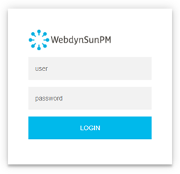 Les accès par défaut sont :
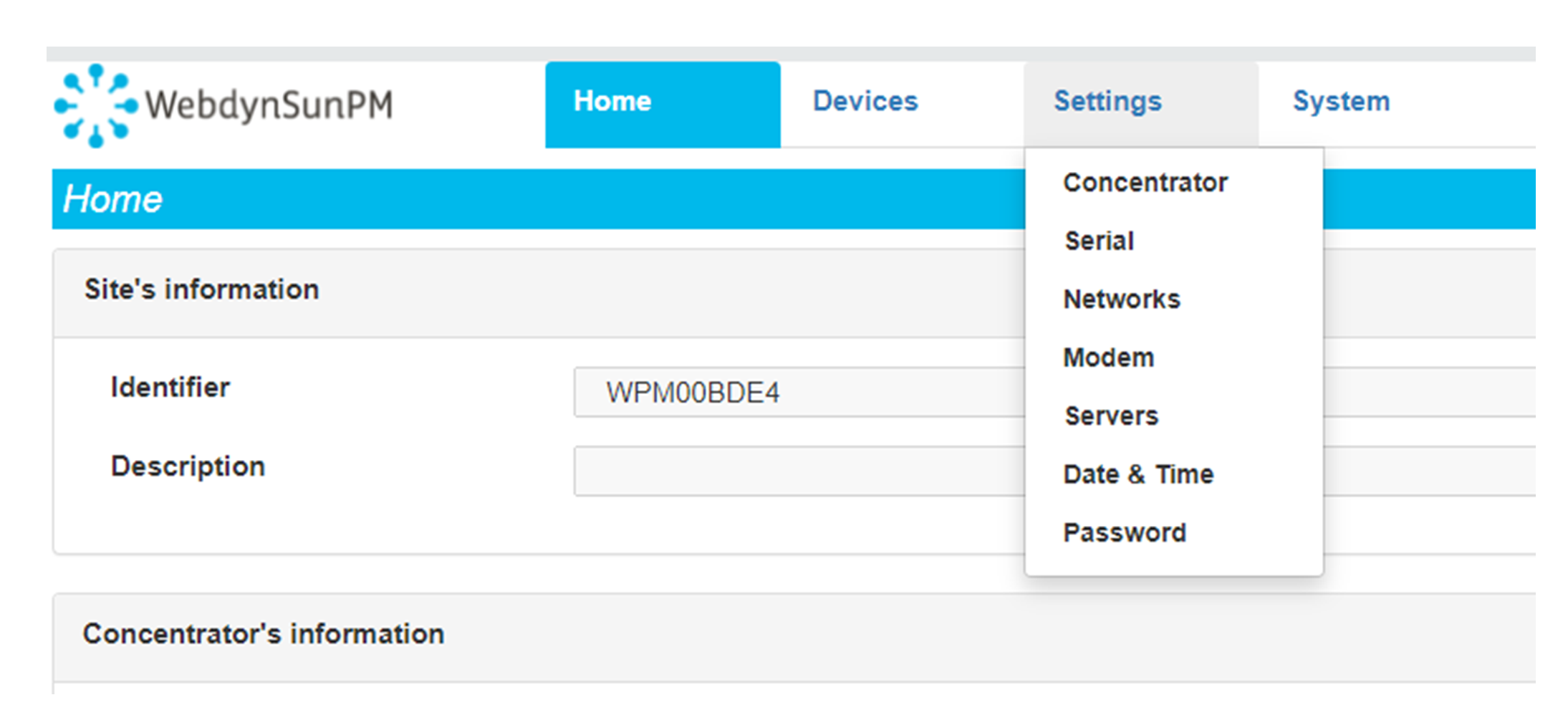 Saisir le mode de connexion « Ethernet » ou « modem » :
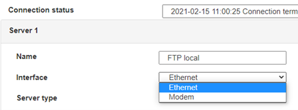 Dans le cas d’une configuration par Ethernet, veiller à ce que les paramètres IP soient compatibles avec l’accès au serveur d’après la configuration du réseau local du concentrateur. Dans le cas d’une connexion par Ethernet, la configuration doit être compatible avec la topologie du réseau local du concentrateur afin qu’il puisse accéder aux serveurs. Cette configuration se fait via la page de configuration « Networks » (voir chapitre 3.2.2.3 : « Réseaux (Networks) »).
Dans le cas d’une connexion par modem, la configuration du modem doit être correcte avant de pouvoir effectuer une connexion. Cette configuration se fait dans la page de configuration « Modem » (voir chapitre 3.2.2.4 : « Modem »).
Les paramètres des serveurs à configurer au minimum sont les suivants :
 Il faut donc configurer les champs : « Interface », « Type », « Server type », « Address », « Port », « Login » et « Password ».
Les autres champs peuvent être laissés aux valeurs par défaut à condition que les répertoires aient été créés correctement auparavant. Voir chapitre 3.1.2 : « Fichiers de configuration » pour plus de détails.


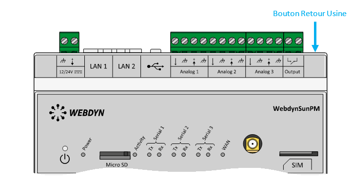 Attendre. Le concentrateur va redémarrer avec sa configuration usine.

