Suchen Sie etwas anderes?
Table of Contents
Scenario Details
In this scenario, there is a computer connected to a modem (analogic o gsm) with a software designed to make conventional data calls (CSD) to remote modems, to read daily the meter boxes.
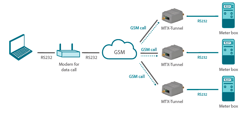
We need to change the daily reading for a reading every 15 min, so we will replace GSM communications for IP communications. But our software does not allow IP communications.
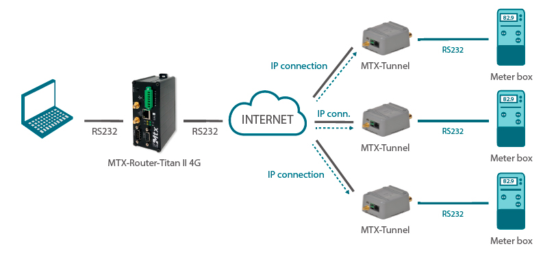
To solve this we replace the modem for MTX-Router-Titan II, since it has a CSD call emulator so we can “convert” CSD calls into IP communications. In order for the system works property, the modems connected to the meter boxes must be MTX (2G, 3G or 4G) with MTX-Tunnel firmware:
Hardware Needed
- MTX-Router-Titan-II-S-3G or MTX-Router-Titan-II-S-4G connected to the PC
- Modem MTX (2G/3G/4G) with MTX-Tunnel firmware connected to the meter boxesIn the following screenshot we need to specify we want to activate the 2G/3G/4G session depending on the state of the router digital input. The router digital input has a dry contact and it can be activated connecting the PIN 13 in the DB15 connector with the PIN 14 (GND). In other words, while PIN 13 is connected to PIN 14, the 3G/4G session will be active. As soon as we disconnect them, the session will be deactivated. We can connect those two pins with a PLC with external relays, or a similar device
Router Titan Configuration
These are the necessary steps to configure the router “CDS-Emulator” plugin.
The MTX-Router-Titan II is connected to the PC via a RS232 cable. We will use the router COM1 port for that connection. We need to adjust the configuration of the router COM1 port to the needed parameters (baudrate, parity…). To do that, we configure the section “Serial Settings >> Serial Port1” the following way.
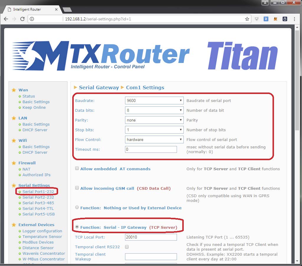
That is, we configure a TCP server on the TCP port 20010 and we will adjust the serial port parameters. Next, we will configure the plugin section “CSD Emulator”. To do that we go to the section “Plugins > CSD_emulator”.
We select the “enabled” box, we will specify the local TCP port of connection (20010, the same from the previous screen) and we will activate the echo (yes or no) depending on the PC control software. If said software needs to manage the modem with the echo enabled, we will activate that box. If not (that would be generally the case), we will not activate it.
Then, enter the remote modems phone numbers and associated IP addresses. For instance, if the phone number 666123456 has a public IP address 2.100.101.102 (listening on the TCP20010 port), the phone number 666123457 the public IP address 2.100.101.103 (listening on the TCP20010 port) and the phone number 666123458 the public IP address 2.100.101.104 (listening on the TCP20010 port), the router configuration would be the following.
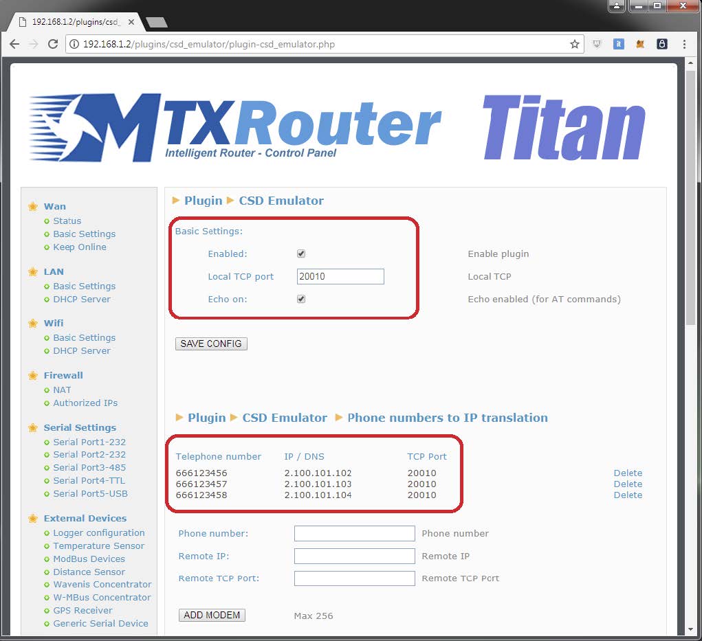
This way, the router would be configured. It needs to be reset just to use it. We do this from the section “Other > Reboot”.
Testing the CSD_Emulator Plugin
Testing the plugin is immediate since we just need to connect the control PC to the router through an RS232 serial cable and test the communication against one of the remote routers. Another way of testing it is opening a hyperterminal on the PC and testing the connection via AT commands.
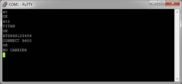
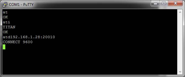
If we want to, the CSD_Emulator plugin allows us to use the ATD command with the format ATDaaa.bbb. ccc.ddd:xxxxx where aaa.bbb.ccc.ddd is the remote IP address and xxxxx the remote TCP port as well as with the usual format ATDxxxxxxxx where xxxxxxx is the phone number to be called.



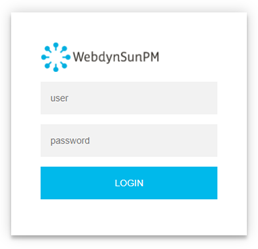 Les accès par défaut sont :
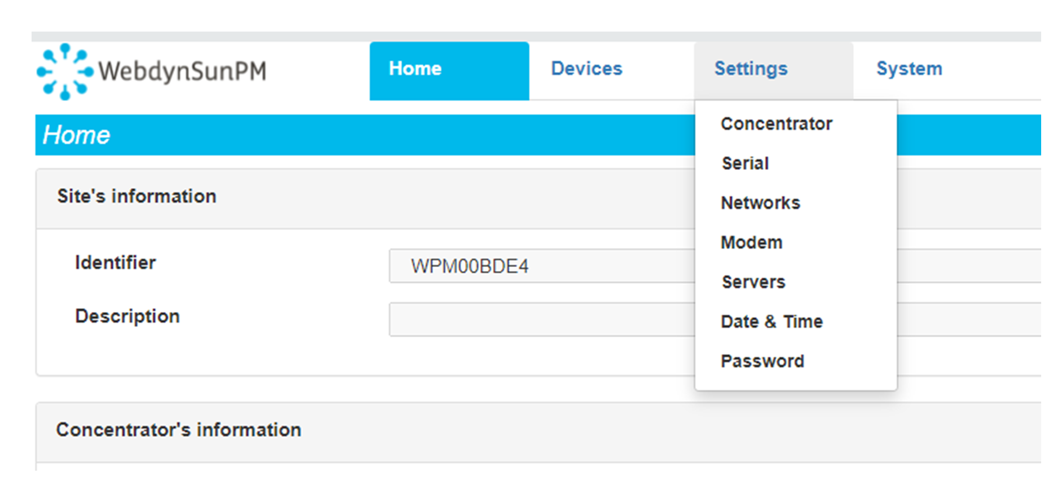 Saisir le mode de connexion « Ethernet » ou « modem » :
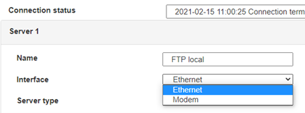 Dans le cas d’une configuration par Ethernet, veiller à ce que les paramètres IP soient compatibles avec l’accès au serveur d’après la configuration du réseau local du concentrateur. Dans le cas d’une connexion par Ethernet, la configuration doit être compatible avec la topologie du réseau local du concentrateur afin qu’il puisse accéder aux serveurs. Cette configuration se fait via la page de configuration « Networks » (voir chapitre 3.2.2.3 : « Réseaux (Networks) »).
Dans le cas d’une connexion par modem, la configuration du modem doit être correcte avant de pouvoir effectuer une connexion. Cette configuration se fait dans la page de configuration « Modem » (voir chapitre 3.2.2.4 : « Modem »).
Les paramètres des serveurs à configurer au minimum sont les suivants :
 Il faut donc configurer les champs : « Interface », « Type », « Server type », « Address », « Port », « Login » et « Password ».
Les autres champs peuvent être laissés aux valeurs par défaut à condition que les répertoires aient été créés correctement auparavant. Voir chapitre 3.1.2 : « Fichiers de configuration » pour plus de détails.


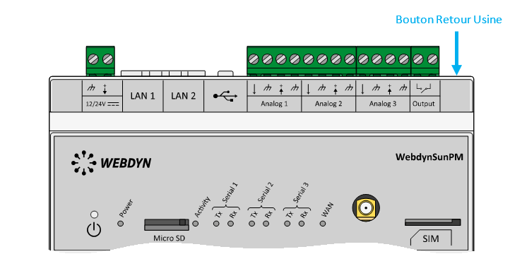 Attendre. Le concentrateur va redémarrer avec sa configuration usine.

