¿Buscas alguna otra cosa?
Detalles del escenario:
- Disponemos de un vehículo a motor (camión) del que se desea monitorizar su posición GPS y la temperatura de 3 sondas de temperatura RS485. El camión también cuenta con un PLC de control, el cual cuenta con un puerto serie RS232. Debe poderse actualizar el firmware del PLC remotamente en cualquier momento por dicho puerto serie RS232
- El módem debe recoger la posición GPS cada 1 minuto y enviarla por JSON a un servidor Web mediante HTTP POST
- El modem debe leer la temperatura de las sondas RS485 cada 10 minutos y enviarla por JSON a un servidor Web mediante HTTP POST
- El modem debe estar preparado para poder actualizar el PLC de control en cualquier momento, para ello debe activar una pasarela 3G-RS232 en el puerto TCP 20010
- El módem debe poderse configurar remotamente por SMS y Telnet
Solución: MTX-Tunnel firmware + MTX-Java-IoT/MTX-Java-T/MTX-Java-T2

Archivo de configuración config.txt:
| Configuración | Ejemplos |
| COMM_baudrate: 19200 COMM_bitsperchar: 8 COMM_autorts: off COMM_autorts: off COMM_stopbits: 1 COMM_parity: none COMM2_baudrate: 9600 COMM2_bitsperchar: 8 COMM2_autorts: off COMM2_autocts: off COMM2_stopbits: 1 COMM2_parity: none GPRS_apn: movistar.es GPRS_login: MOVISTAR GPRS_password: MOVISTAR GPRS_timeout: 0 MTX_PIN: 0000 MTX_mode: server MTX_model: MTX-4G-JAVA-IOT-N-GPS MTX_portAux: modbusmaster MTX_TPProtocol: ntp MTX_TPServer: ntp.roa.es MTX_TPServer2: es.pool.ntp.org MTX_ping: 35 MTX_pingIP: 8.8.8.8 MTX_rssiLevel: 10 MTX_serverTimeout: 300 TCP_port: 20010 SMS_allPhones: on SMS_sendIP: on SMS_ATEnabled: on SMS_ATResponse: on FIREWALL_enabled: off TELNET_enabled: on TELNET_login: user TELNET_password: 1234 TELNET_port: 20023 LOGGER_enabled: on LOGGER_password: ID001 LOGGER_server: dominio.com/datos.asp?datos= LOGGER_registerSize: 300 LOGGER_numRegistersFlash: 1500 LOGGER_httpMode: postjson MODBUS_address: 1;2;3 MODBUS_start: 1;1;1 MODBUS_numwords: 1;1;1 MODBUS_period: 300 MODBUS_readCommand: 4;4;4 MODBUS_regType: 2;2;2 GPS_period: 60 DNS_enabled: on DNS_password: ID00001 DNS_server: www.miservidorWeb.com/json.asp DNS_mode: http DNS_httpMode: postjson DNS_period: 3600 |
Serial port baud rate (PLC HMI communication) Number of bits No flow control No flow control 1 stop bit No parity Serial port baud rate Number of bits No flow control No flow control 1 stop bit No parity APN of SIM card GPRS Login GPRS Password Modem is always GPRS connected SIM Card PIN 3G-RS232 gateway configured for the current PLC MTX modem model The aux port used as master modbus MTX Time synch. protocol Time server (the MTX must sync the time) Backup time server Ping every 35 minutes without comms IP address to ping Coverage led of MTX-65i activated If no gateway traffic in 300s socket server closed Principal serial port gateway RS232 All phone numbers are authorized IP sent to phone which called or “on” SM Remote AT commands by SMS enabled Modem response to AT command with SMS Any IP will be able to connect to the modem Telnet is activated Telnet login Telnet password Telnet port 20023 We enable the MTX Logger, to store the records Field to identify the origin of the frames Server URL, will receive JSON data Register size Maximum number of records in MTX HTTP POST mode (JSON) selected Modbus addresses to be read Initial address of each sensor to be read Registers number to be read Period in seconds within which a reading is done Sensors read with modbus 0x04 command The registers have 2 bytes (unsigned word) Every minute one GPS position is read DNS service activated to inform periodically Field says where frames come from URL to send the JSON with data Configuration mode http HTTP POST is used to send data Status sent everytime IP changes or every 3600s |
Detalles:
- El formato del objeto JSON que el MTX-Tunnel enviará al servidor web, será análogo a la siguiente estructura, para la sonda 1 (23.0º):
{“IMEI”:353234028103206,”P”:”ID00001”,”TYPE”:”MODB”,”A”:1,”TS”:”20/04/13 08:31:44”,”ST”:1, “V1”:230}- para la sonda 2 (24.5º):
{“IMEI”:353234028103206,”P”:”ID00001”,”TYPE”:”MODB”,”A”:2,”TS”:”20/04/13 08:31:44”,”ST”:1, “V1”:245}- para la sonda 3 (22.1º):
{“IMEI”:353234028103206,”P”:”ID00001”,”TYPE”:”MODB”,”A”:2,”TS”:”20/04/13 08:31:44”,”ST”:1, “V1”:221}- Y para las tramas GPS:
{“IMEI”:357044060013890,”TYPE”:”GPS”,”P”:”ID00001”,”DATE”:”2016/10/30”, “TIME”:”21:35:51”,”LAT”:”41.629803”,”NS”:”N”,”LON”:”2.3609767”,”EW”:”E”, ”ALT”:”197.61”,”SPE”:”2.98”,”COU”:”9.85”,”STA”:”3”,”HPO”:”1.25”,”VDO”:”0.75”, “SAT”:”05”}- Donde:
IMEI: es el IMEI del módem
TYPE: indica el tipo de trama de datos
P: es el texto indicado en el parámetro LOGGER_password
DATE: fecha UTC recogida directamente del GPS
TIME: es la hora UTC recogida directamente del GPS
LAT: latitud
NS: N= norte, S= sur
LON: longitud
EW: E= este, W= oeste
ATL: altura
SPE: velocidad
COU: dirección (0–359º)
STA: GPS status (0= no fix, 2= 2D, 3= 3D)
HPO: precisión horizontal (mejor cuanto más próximo a 1)
VDO: precisión vertical (mejor cuanto más próximo a 1)
SAT: nº de satélites
- Recuerde que el modelo de módem utilizado en este ejemplo dispone de 2 puertos serie.
El puerto principal (RS232) y el puerto secundario (RS232 ó RS485) también utilizado
en este ejemplo. Para configurar el puerto secundario como RS485 debe poner a “ON” el
microswitch 2, tal y como se indica en el Anexo A del presente manual


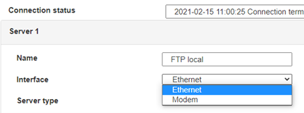
 Ingresar el modo de conexión «ethernet» o «módem»:
 En el caso de una configuración por ethernet, tener el cuidado de que los parámetros IP sean compatibles con el acceso al servidor según la configuración de la red local del concentrador. En el caso de una conexión por ethernet, la configuración debe ser compatible con la topología de la red local del concentrador para que pueda acceder a los servidores. Esta configuración se hace a través de la página de configuración «Networks» (ver capítulo 3.2.2.3: «Redes (Networks)«).
En el caso de una conexión por módem, la configuración del módem debe ser correcta antes de poder efectuar una conexión. Esta configuración se hace en la página de configuración «Modem» (ver capítulo 3.2.2.4: «Módem«).
Los parámetros de los servidores a configurar como mínimo son los siguientes:
 Por lo tanto, hay que los campos: «Interface», «Type», «Server type», «Address», «Port», «Login» y «Password».
Los otros campos se pueden dejar a los valores por defecto, a condición de que los repertorios hayan sido creados antes correctamente. (Ver capítulo 3.1.2 : «Archivos de configuración« para más detalles.


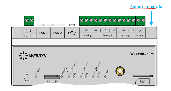
 Esperar. El concentrador arrancará con su configuración de fábrica.


