¿Buscas alguna otra cosa?
Description of I/O interfaces:
- DB15 expansion connection: 3 digital inputs (2 of them pulse counters), 2 digital outputs and 2 A/D conversors (0-50V in tension mode, 0-20mA in current mode)
- Serial interfaces: 1x RS232 (DB9), 1x RS232 (DB15) or 1x RS485 (configurable with switches)
- MTX-Tunnel software uses inputs/outputs the following way:
| GPIO | LOCATION | PIN | I/O | FUNCTION | @MODBUS |
| GPIO1 | DB15 | 4 | Digital input | Wake up/pulse counter | 1/13-14 |
| GPIO2 | DB15 | 11 | Digital input | SMS alarm/pulse counter | 2/15-16 |
| GPIO3 | DB15 | 9 | Digital input | User/pulse counter | 3/17-18 |
| GPIO4 | DB15 | 5 | Digital output | User | 4 |
| GPIO5 | DB15 | 12 | Digital output | User | 5 |
| ADC1 | DB15 | 15 | Analog input | User | 11 |
| ADC2 | DB15 | 13 | Analog input | User | 12 |
| VExt | DB15 | 10 | Output voltage | 4V | — |
| GND | DB15 | 14 | Ground | Ground | — |
- The column “GPIO” indicates the virtual GPIO corresponding to the GSM module inside the modem
- The column “Location” indicates in which connector of the modem the I/O is located
- The column “Nº PIN” indicates in which pin of DB15 connector the I/O is located
- The column “I/O” indicates I/O type
- The column “Function” indicates if GPIO has a special task inside MTX-Tunnel. If neither “Wake up” nor “SMS alarm” are used, you can use the digital inputs GPIO20 and GPIO21 as user’s digital inputs. If the options ‘Wake up” and “SMS alarm” are used, MTX-Tunnel uses the inputs GPIO20 and GPIO21
- The parameters OUTPUT_xxx1 refer to PIN 5 of DB15 connector
- The parameters OUTPUT_xxx2 refer to PIN 12 of the connector DB15
- GPIO20 and GPIO21 are optoisolated inputs that can be activated by GND (PIN 14 of DB15 connector). GPIO7 is a digital input CMOS activated by VOUT (PIN 10) of DB15 connector
Jumpers configuration
The modem has serveral switches that allow several configurations:
- [SW1 off] + [SW2 on]: RS232 DB9 on, RS232 DB15 off, RS485 on
- [SW1 off] + [SW2 off]: RS232 DB9 on, RS232 DB15 on, RS485 off
- [SW7 off]: voltage analog input 1 (0-50V)
- [SW7 on]: current analog input 1 (0-20mA)
- [SW8 off]: voltage analog input 2 (0-50V)
- [SW8 on]: current analog input 2 (0-20mA)


| PIN | SIGNAL | DIRECTION | LIMITS | DESCRIPTION |
| 1 | -RxB | I/O | RS485 B signal (see section Interface Description 5 (RS485 bus) for details) |
|
| 2 | +RxA | I/O | RS485 A signal (see section Interface Description 5 (RS485 bus) for details) |
|
| 3 | NC | Not connected | ||
| 4 | VIN | Input | 7-50VDC | Positive power input |
| 5 | GND | Input | Negative power (ground) |


 Ingresar el modo de conexión «ethernet» o «módem»:
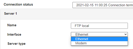 En el caso de una configuración por ethernet, tener el cuidado de que los parámetros IP sean compatibles con el acceso al servidor según la configuración de la red local del concentrador. En el caso de una conexión por ethernet, la configuración debe ser compatible con la topología de la red local del concentrador para que pueda acceder a los servidores. Esta configuración se hace a través de la página de configuración «Networks» (ver capítulo 3.2.2.3: «Redes (Networks)«).
En el caso de una conexión por módem, la configuración del módem debe ser correcta antes de poder efectuar una conexión. Esta configuración se hace en la página de configuración «Modem» (ver capítulo 3.2.2.4: «Módem«).
Los parámetros de los servidores a configurar como mínimo son los siguientes:
 Por lo tanto, hay que los campos: «Interface», «Type», «Server type», «Address», «Port», «Login» y «Password».
Los otros campos se pueden dejar a los valores por defecto, a condición de que los repertorios hayan sido creados antes correctamente. (Ver capítulo 3.1.2 : «Archivos de configuración« para más detalles.


 Esperar. El concentrador arrancará con su configuración de fábrica.

