Suchen Sie etwas anderes?
Description of I/O interfaces:
- DB15 expansion connection: 3 digital inputs (2 of them pulse counters), 2 digital outputs and 2 A/D conversors (0-50V in tension mode, 0-20mA in current mode)
- Serial interfaces: 1x RS232 (DB9) or 1x RS485 (configurable with switches)
- Wavecard 868MHz: internal radio card, connected to secondary port
- MTX-Tunnel software uses these inputs/outputs as follows:
| GPIO | LOCATION | PIN | I/O | FUNCTION | @MODBUS |
| GPIO1 | DB15 | 4 | Digital input | Wake up/pulse counter | 1/13-14 |
| GPIO2 | DB15 | 11 | Digital input | SMS alarm/pulse counter | 2/15-16 |
| GPIO3 | DB15 | 9 | Digital input | User/pulse counter | 3/17-18 |
| GPIO4 | DB15 | 5 | Digital output | User | 4 |
| GPIO5 | DB15 | 12 | Digital output | User | 5 |
| ADC1 | DB15 | 15 | Analog input | User | 11 |
| ADC2 | DB15 | 13 | Analog input | User | 12 |
| VExt | DB15 | 10 | Output voltage | 4V | — |
| GND | DB15 | 14 | Ground | Ground | — |
- The column “GPIO” indicates the virtual GPIO corresponding to the GSM module inside the modem
- The column “Location” informs us which modem connector is located the I/O
- The column “Pin number” tells us the I/O terminal block or connector pin number
- The column “I/O” tells us if the GPIO is an input (digital or analog) or a digital output
- The column “Function” tells us if the GPIO has special features in MTX-Tunnel. If it doesn’t use “SMS alarm” or “Wake up” you can use GPIO1 and GPIO2 as user digital inputs.If it uses them, digital inputs are used by the MTX-Tunnel
- The parameters OUTPUT_xxx1 refer to PIN 5 of the DB15 connector
- The parameters OUTPUT_xxx2 refer to PIN 12 of the DB15 connector
- GPIO1 and GPIO2 are optoisolated inputs that can be activated via GND (PIN 14 of the DB15 connector). GPIO3 is a CMOS digital input, activated via VOUT (PIN 10) of the DB15 connector
Jumpers configuration
The modem has serveral switches that allow several configurations:
- [SW5 off] + [SW2 on] + [SW1 on]: RS232 DB9 on, RS232 DB15 off, RS485 off
- [SW5 on] + [SW2 off] + [SW1 off]: RS232 DB9 off, RS232 DB15 off, RS485 on
- [SW7 off]: voltage analog input 1 (0-50V)
- [SW7 on]: current analog input 1 (0-20mA)
- [SW8 off]: voltage analog input 2 (0-50V)
- [SW8 on]: current analog input 2 (0-20mA)


| PIN | SIGNAL | DIRECTION | LIMITS | DESCRIPTION |
| 1 | -RxB | I/O | RS485 B signal | |
| 2 | +RxA | I/O | RS485 A signal | |
| 3 | ||||
| 4 | VIN | Input | 6.5-40VDC | Positive power input |
| 5 | GND | Input | Negative power (ground) |



 Geben Sie den Verbindungsmodus „ethernet“ oder „modem“ ein:
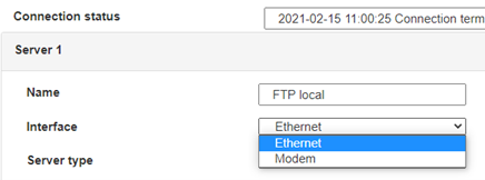 Stellen Sie bei einer Ethernet-Konfiguration sicher, dass die IP-Parameter mit dem Serverzugriff entsprechend der lokalen Netzwerkkonfiguration des Hubs kompatibel sind. Bei einer Ethernet-Verbindung muss die Konfiguration mit der lokalen Netztopologie des Hubs kompatibel sein, damit dieser auf die Server zugreifen kann. Diese Konfiguration erfolgt über die Konfigurationsseite „Networks“ (siehe Kapitel 3.2.2.3: „Netzwerke (Networks)“).
Bei einer Modemverbindung muss das Modem korrekt konfiguriert sein, bevor eine Verbindung hergestellt werden kann. Diese Konfiguration erfolgt auf der Konfigurationsseite „Modem“ (siehe Kapitel 3.2.2.4: „Modem“).
Die minimal zu konfigurierenden Serverparameter sind folgende:
 Diese Felder müssen konfiguriert werden: „Interface“, „Type“, „Server type“, „Address“, „Port“, „Login“ und „Password“.
In den übrigen Feldern können die Standardwerte beibehalten werden, solange die Verzeichnisse zuvor korrekt angelegt wurden. Weitere Einzelheiten siehe Kapitel 3.1.2: „Konfigurationsdateien“.


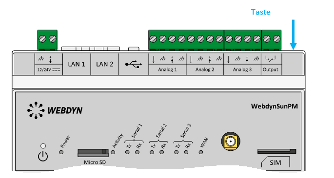 Warten Sie. Der Hub startet nach ein paar Augenblicken mit der Werkseinstellung neu.

