Suchen Sie etwas anderes?
Table of Contents
Scenario Details
This application note shows, step by step, how to carry out a scenario in which data sent by LoRa sensors, using a Titan router such as Gateway LoRa-2G / 3G / 4G, to a data collection and management platform such as Cervello, which will also act as Device Manager for the Titan router.
Description of the Example
It is necessary to install a network of dozens of LoRa sensors distributed in a wide area of cultivation of 10 km radius. Digital input sensors are needed to monitor the opening of doors and hatches, as well as 0-10V and 4-20mA analog input sensors to monitor parameters such as humidity, temperatures, well levels, etc.
The sensors will not have external power, so they must have an internal battery and the autonomy of this must last several years. In order to save energy, digital and analog sensors must be able to be configured to send their reading data in two ways to a Management Platform, from where all the data received from the sensors must be managed and visualized as well as reports generated, alerts, etc.
The two reasons that will cause a LoRa sensor to send data should be:
- When an event occurs (such as a change in a digital input or a threshold exceeded in an analog input)
- For security, you must send your status every 12 hours
Due to the requirements of this scenario, the resolution approach is raised with the following devices / services:
LORA SENSORS:
ARF8170BA LoRa sensor with 4 digital inputs
ARF8190BA LoRa sensor with 2 configurable 4-20mA or 0-10V analog inputs
These battery-powered LoRa sensors allow the previously indicated sending configuration, that is, sending their data in the event of an event and / or periodically.
GATEWAY LORA:
MTX-Router-Titan-4G-LoRa, Gateway LoRa Capable 4G Router
This 4G router has the LoRa-IP Gateway capability (where IP communications can be routed through Ethernet, Wifi or 2g / 3g / 4g). In the case of the present example, the routing by 2g / 3g / 4g will be chosen. That is, this Titan router will collect the LoRa data emitted by the sensors in its range of action and will forward them to the LoRa server in TTN.
This Titan router also allows to be managed remotely in multiple ways (SMS, IP, Openvpn, Modbus TCP or, the most comfortable, from the Cervello Platform).
SERVER LORA:
TTN: The Things Network, a platform that will carry out the LoRa Server mission to manage the Device Network. It will be the part that is in charge of collecting the data from the sensors relayed by the Titan router.
DEVICE MANAGER PLATFORM AND SENSOR DATA TREATMENT:
Cervello: The Cervello platform manages the reception of sensor data from the TTN server. In other words, Cervello connects to TTN and, via MQTT, receives all the data from the LoRa sensors, storing them in its Database. In addition, it provides the visualization of the sensor data through gauges, allows the generation of the pertinent reports, generates alarms (SMS, emails, etc.) based on the data received from the sensors, etc.
It also performs the function of Device Manager of the Titan routers, allowing their remote management.
The following shows how to configure the different elements of the described scenario.
Configuration of Titan router as LoRa-2G/3G/4G Gateway
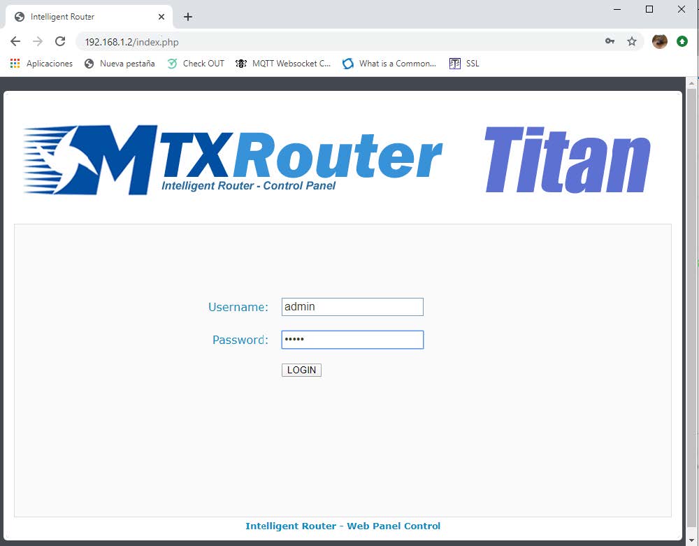
The first thing to do on the Titan router is to configure 2g / 3g / 4g connectivity. For this, you must enter the Titan router configuration through its default IP address 192.168.1.2 and user / password admin / admin.
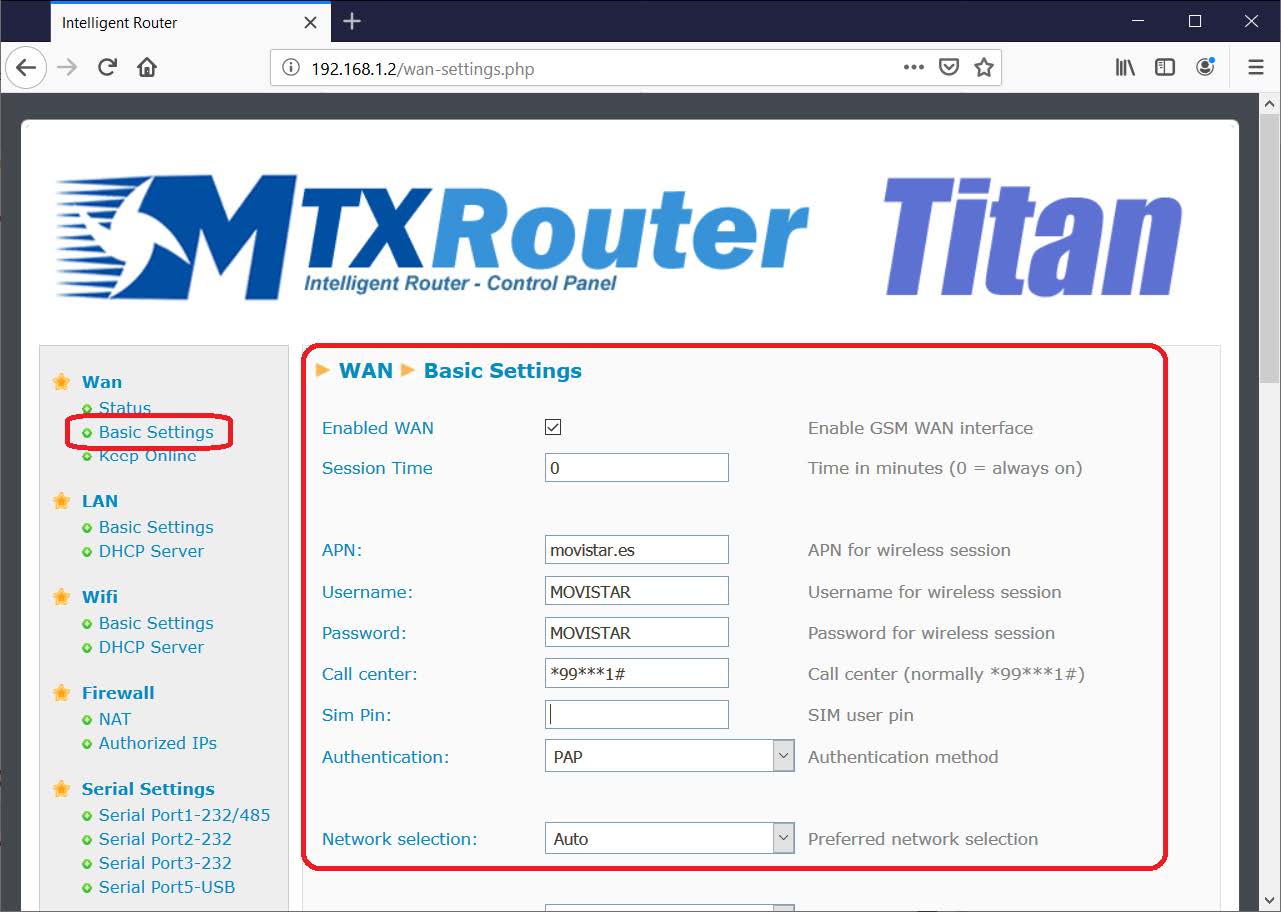
To configure the Internet access of the TITAN router via SIM card, you must access the router\’s configuration menu WAN > Basic Settings
Once in this configuration screen, enter the parameters Sim PIN of the SIM card (if you have the PIN), and the APN, Username and Password of the operator used. Once this is done press the SAVE CONFIG button. Finally, restart the router (Other > Reboot menu) so that the Titan router starts up with the new settings and proceeds to connect to the Internet.
Once connected to the Internet, access the configuration menu “Other > LoRa Gateway” and enter the configuration as indicated below, specifying the Latitude / Longitude of where the Gateway will be located and selecting the “Gateway Lora – Packet Forwader” mode) .
Then enter a unique ID for the Gateway with 8 hexadecimal characters (in the example 010203040A0B0C0D). Where it indicates server address, enter router.eu.thethings.network (if your router will not be in Europe, search TTN for the most appropriate DNS). Finally complete the rest of the parameters as shown in the next screen. Once this screen is configured, save the changes and restart the Titan router.
Gateway Registration Configuration in TTN
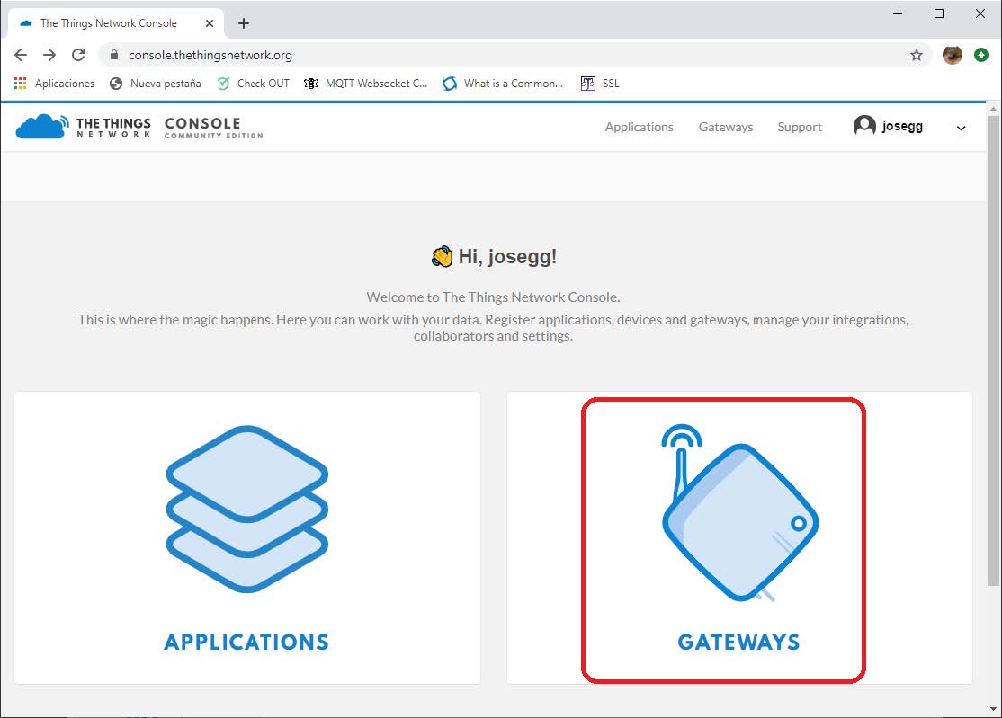
This section assumes that the user has registered at www.thethingsnetwork.org. Once registered, the console section must be accessed: console.thethingsnetwork.org Once inside the console, the “Gateways” option must be selected. This will configure the TTN service to accept the connection from the Titan router as a LoRa Gateway.
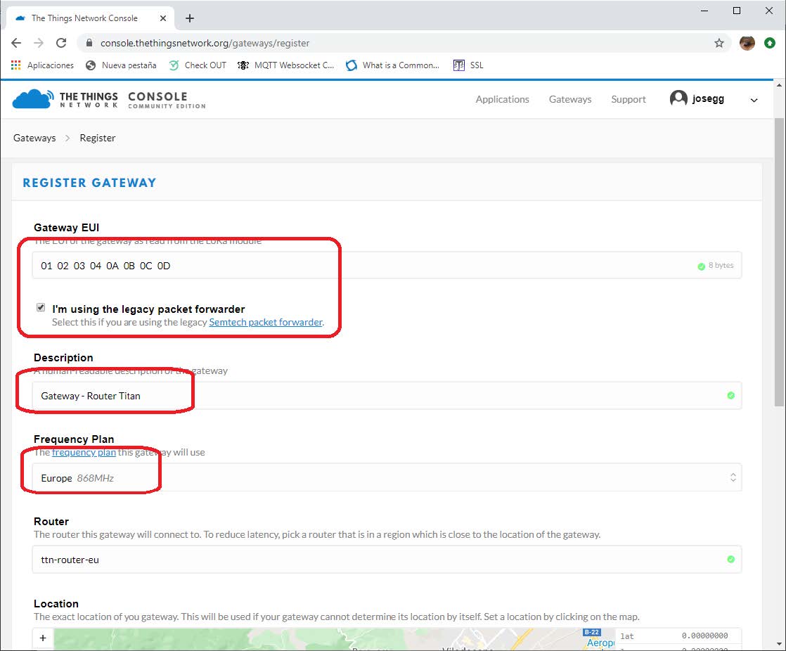
Once inside Gateway, click on register gateway and proceed to enter the Titan router parameters. In the Gateway EUI box, enter the Gateway ID that was entered during the Titan router configuration process (in the example, 010203040A0B0C0D). A description must also be entered as well as the working frequency (Europe = 868MHz).
After completing the Gateway registration process (Titan router), after a few seconds the Gateway should appear as “Connected” as shown in the following figure. At this point the Gateway (Titan router) is already correctly connected with the TTN platform).
Setting Up an Application in TTN
In order to register the different LoRa sensors, an application must be created in TTN. To do this, in the console, you must go to the Applications menu. Once there, click on the link Create application.
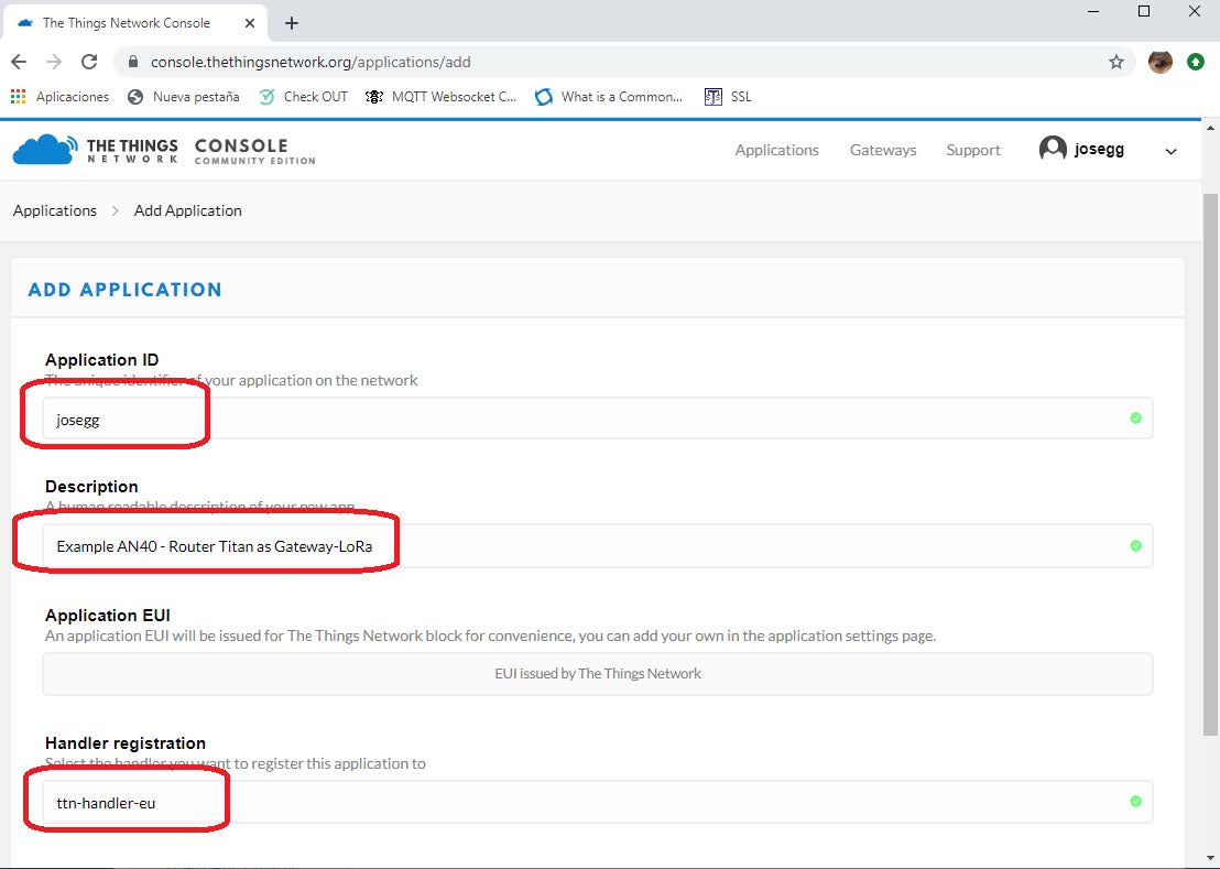
Complete the Application ID fields (with a unique identifier of your choice), a description and the most appropriate handler.
The next screen shows the data to be completed.
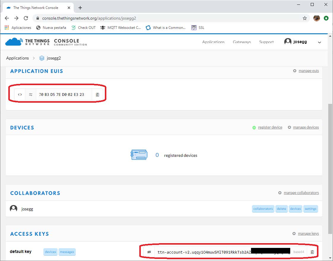
Once the Application is created, it must be noted that: the Application EUI (as it must be specified in the sensors configuration to indicate which application to send the data to) and the Access Key of the application (as it will be necessary to communicate the Cervello platform with TTN).
LoRa Sensors Registration in TTN Application
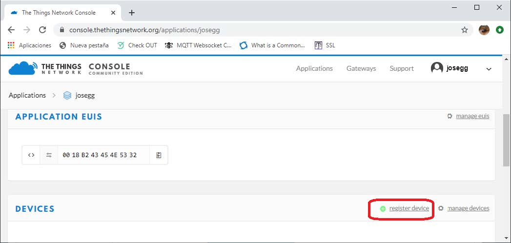
In the same screen above, click on “register device” to register the different LoRa sensors in the newly created application.
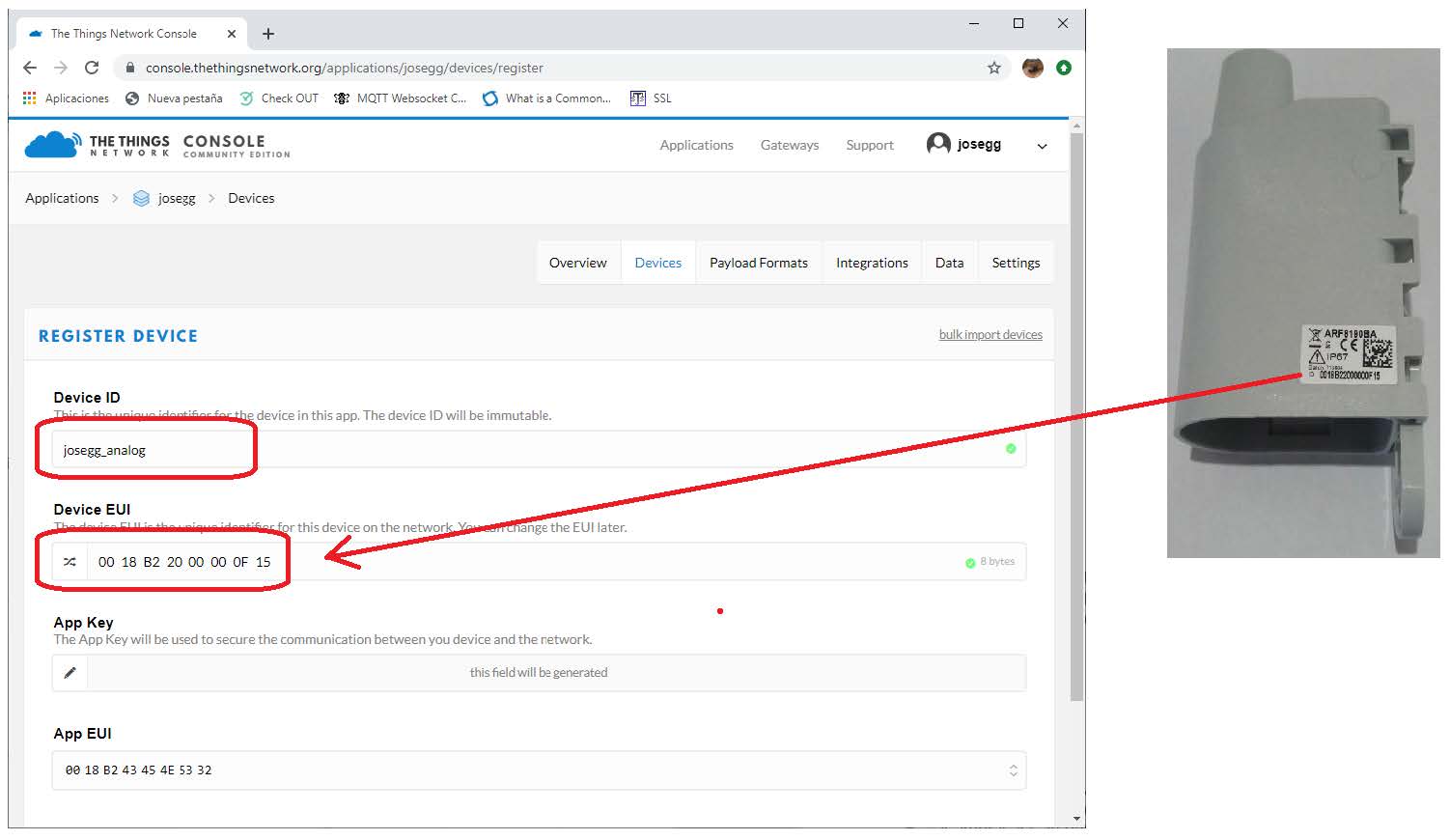
For each sensor, enter a “Device ID” and the “Device EUI”. This last parameter is an identifying number that is printed on the attached label of each sensor.
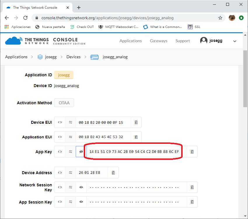
Once the sensor is created, the APP Key must be noted, as it will also need to be entered in the sensor configuration.
LoRa Sensors Configuration
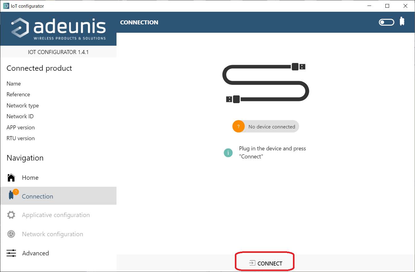
The most convenient way to configure Adeunis LoRa sensors is to use the Adeunis PC configuration application “IOT CONFIGURATOR”. Simply connect the LoRa sensor via a USB cable to access its configuration by pressing the CONNECT button. You will find the microUSB connector of the LoRa sensor by opening the sensor from its bottom.
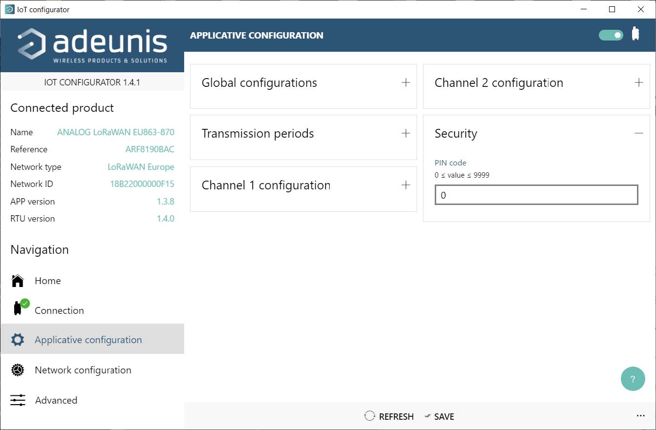
Once inside the configuration there are two sections to configure. On the one hand Applicative Configuration, where the behavior of the sensor will be indicated, and on the other hand Network Configuration, with the network configuration. In “Applicative Configuration” several menus to configure will be displayed.
In Global Configurations you must specify Production, in Transmission periods you must specify how many seconds the sensor should transmit its data periodically. If you want them to send their status every 12 hours, you must specify 12×60 / 20 = 72.
In the Channel X configuration menus, the behavior of the analog and digital channels must be configured, depending on the type of sensor. That is, it sends analog measurements when they exceed a certain threshold, or when a digital sensor changes state, according to needs.
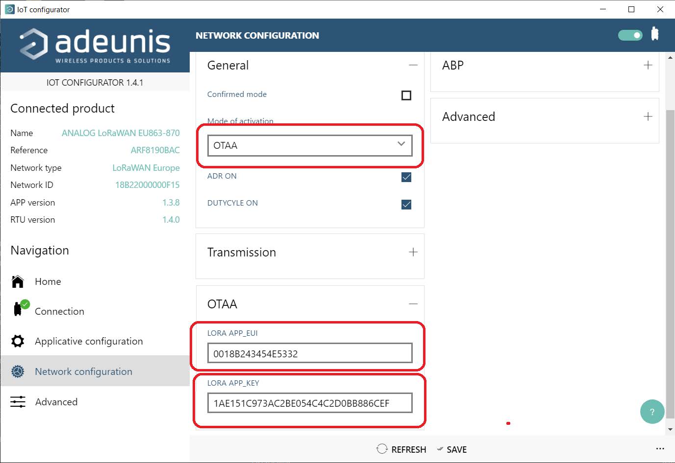
Then the Network configuration section must be configured. The activation mode OTAA must be specified in the General section. In the OTAA section, the “Application EUI” that was noted during the creation of the Application in TTN (section 4 of this application note) as well as the parameter “LORA_APP_KEY” generated in section 5 of this note must be specified. Note that LORA_APP_KEY is different for each registered sensor.
From this point on it is already possible to obtain data from the sensors configured in TTN each time any of them emit data.
Receiving Data from LoRa Sensors on the Cervello Platform
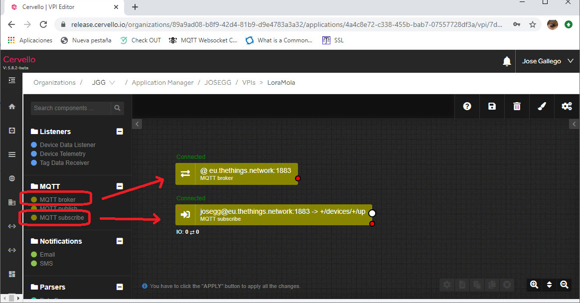
To receive the data from the LoRa Sensors in Cervello, it is only necessary to create a VPI and add 2 components to it. An “MQTT broker” component, which will be configured to connect with the TTN MQTT broker, and an “MQTT subscribe” component, used to subscribe to the appropriate TTN topic that will receive the data from the LoRa sensors associated with the application. created.
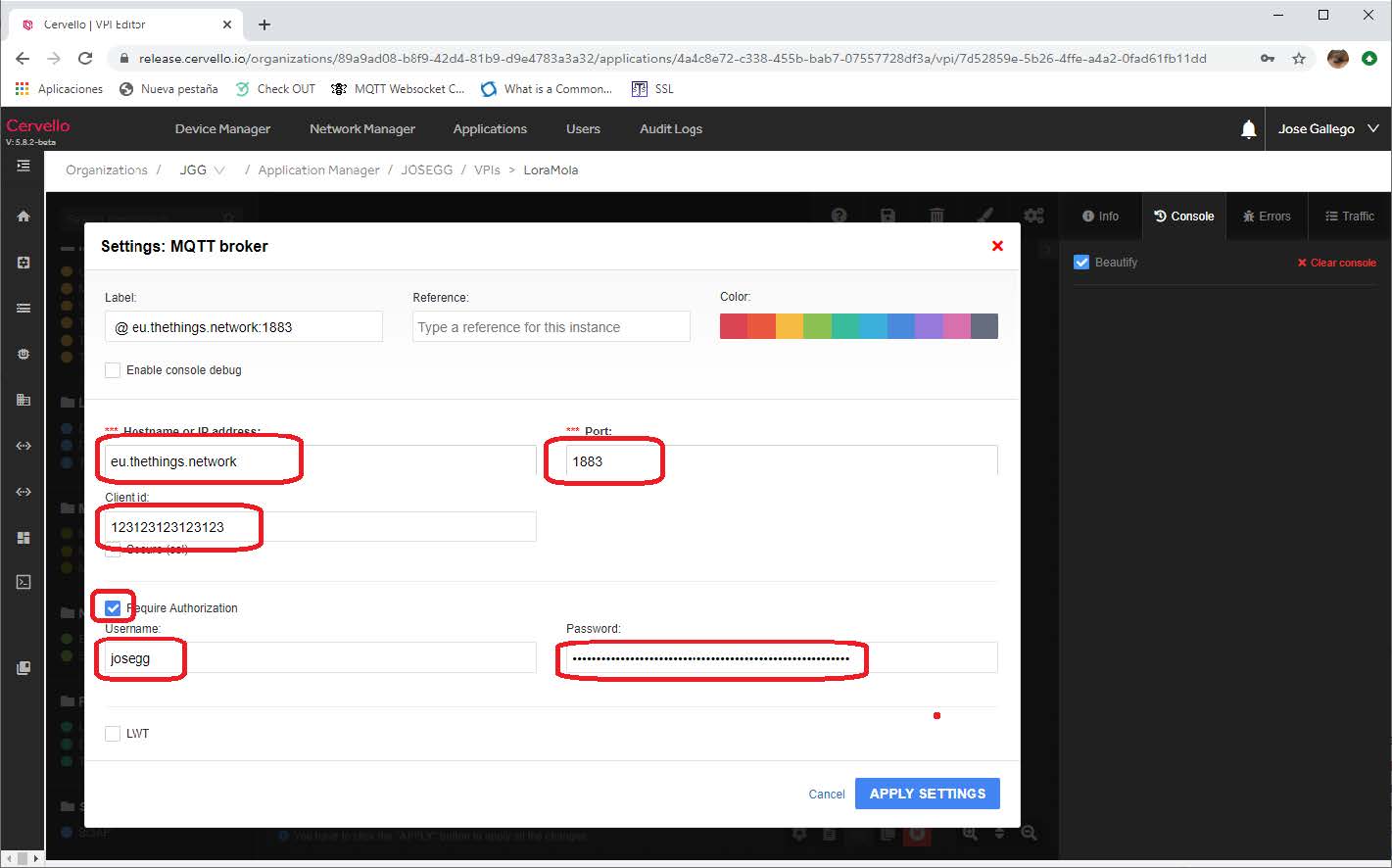
The configuration of the Broker MQTT component will be as follows:
In “hostname” you must enter the broker indicated in TTN (in Europe “eu.thethings.network”). In Port the port 1883 will be indicated. In the parameter Client ID a unique identifier for the MQTT client that is being configured must be indicated, and in password the Access KEY that was noted at the end of the point 4 of this application note.
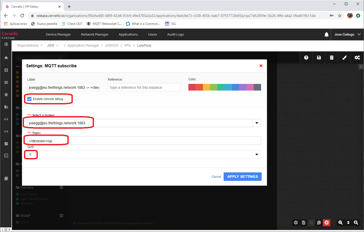
Finally, the component “MQTT subscribe” must be configured as described in the previous figure. In “Select a broker”, the name of the “MQTT broker” component that has just been created must be chosen. In Topic you must enter the topic specified in TTN for receiving data from LoRa sensors, which is generically: + / devices (+ / up. You must also click on the Enable Console Debug checkbox, since in this way it will be possible to visualize the frames received from the LoRa sensors in the debug section.
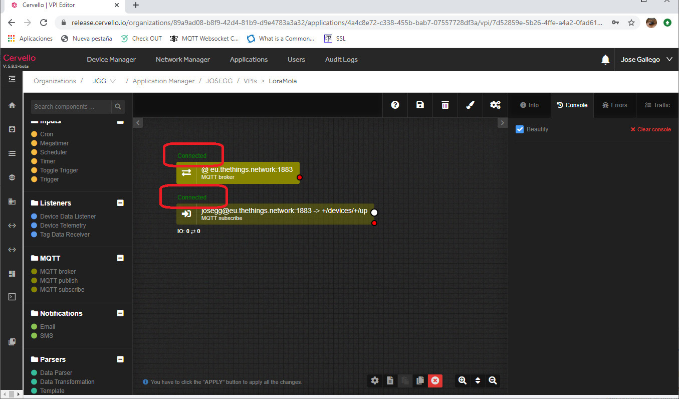
If everything has been configured correctly, “Connected” should be displayed on both components.
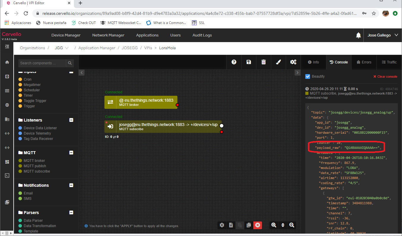
The right section of the screen is where the debug is located. When devices transmit data, they should be shown in that section as shown in the following figure.
Note that when receiving data from a sensor a field of the received JSON object has the name payload_raw. This parameter contains the data (payload) sent by the sensor. In the case of the example, it shows the data of an analog sensor ARF8190BA. This data is configured in Base64, which can be easily decoded. Following this example, the QiARAAAAIQAAAA == data is decoded from Base64 as:
42 20 11 00 00 00 21 00 00 00
The values indicated in red being the value of the 2 analog inputs of the sensor as specified in the Adeunis ARF8190BA sensor manual.
For any questions, contact us at iotsupport@mtxm2m.com.







 Geben Sie den Verbindungsmodus „ethernet“ oder „modem“ ein:
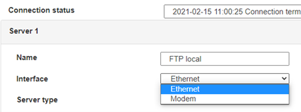 Stellen Sie bei einer Ethernet-Konfiguration sicher, dass die IP-Parameter mit dem Serverzugriff entsprechend der lokalen Netzwerkkonfiguration des Hubs kompatibel sind. Bei einer Ethernet-Verbindung muss die Konfiguration mit der lokalen Netztopologie des Hubs kompatibel sein, damit dieser auf die Server zugreifen kann. Diese Konfiguration erfolgt über die Konfigurationsseite „Networks“ (siehe Kapitel 3.2.2.3: „Netzwerke (Networks)“).
Bei einer Modemverbindung muss das Modem korrekt konfiguriert sein, bevor eine Verbindung hergestellt werden kann. Diese Konfiguration erfolgt auf der Konfigurationsseite „Modem“ (siehe Kapitel 3.2.2.4: „Modem“).
Die minimal zu konfigurierenden Serverparameter sind folgende:
 Diese Felder müssen konfiguriert werden: „Interface“, „Type“, „Server type“, „Address“, „Port“, „Login“ und „Password“.
In den übrigen Feldern können die Standardwerte beibehalten werden, solange die Verzeichnisse zuvor korrekt angelegt wurden. Weitere Einzelheiten siehe Kapitel 3.1.2: „Konfigurationsdateien“.


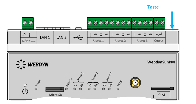 Warten Sie. Der Hub startet nach ein paar Augenblicken mit der Werkseinstellung neu.

