Suchen Sie etwas anderes?
Scenario details:
- It is necessary to control 8 fans of a farm autonomously. Each fan has an associated Modbus RTU protocol temperature probe, with RS485 connection
- When the Temperature Sensor X is above 30 degrees, the associated Fan X should be activated to facilitate air circulation and lower the temperature of the room. When Temperature Sensor X detects a temperature of 25 degrees, Fan X must be deactivated again. In this way, each farm enclosure will always be between 25 and 30 degrees
- In addition to activating the fans, a MQTT platform must be informed in real time each time a fan is activated / deactivated, in order to have constantly updated information on the application dashboard. Loss of communications with the MQTT control platform must not interfere with the control of the fans
Solution: MTX-Tunnel firmware + MTX-IOT-S [4-N]
Configuration example (config.txt file) for the indicated scenario:
| Configuration | Observations |
| COMM2_baudrate: 9600 COMM2_bitsperchar: 8 COMM2_autorts: off COMM2_autocts: off COMM2_stopbits: 1 COMM2_parity: none GPRS_apn: movistar.es GPRS_login: MOVISTAR GPRS_password: MOVISTAR GPRS_timeout: 0 MTX_pin: 0000 MTX_model: 199802407 MTX_mode: none MTX_ping: 30 MTX_pingIP: 8.8.8.8 MTX_numGSMErrors: 180 MTX_portAux: modbusmaster MQTT_enabled: on MQTT_server: tcp://broker.mqttdashboard.com:1883 MQTT_id: [IMEI] MQTT_login: MQTT_password: MQTT_attopic1: [IMEI]/AT MQTT_atrtopic: [IMEI]/ATR MQTT_persistent: off MQTT_qos: 1 MQTT_keepalive: 60 MQTT_defaultOTopic: /IOCHANGE MQTT_defaultIOQos: 1 GPIO_mode0: output GPIO_config0: modbus;10;3;1;250;300;; GPIO_mode1: output GPIO_config1: modbus;11;3;1;250;300;; GPIO_mode2: output GPIO_config2: modbus;12;3;1;250;300;; GPIO_mode3: output GPIO_config3: modbus;13;3;1;250;300;; GPIO_mode4: output GPIO_config4: modbus;14;3;1;250;300;; GPIO_mode5: output GPIO_config5: modbus;15;3;1;250;300;; GPIO_mode6: output GPIO_config6: modbus;16;3;1;250;300;; GPIO_mode7: output GPIO_config7: modbus;17;3;1;250;300;; |
Data rate of communication of serial port Number of bits CTS Hardware flow control deactivated RTS Hardware flow control deactivated 1 stop bit No parity GPRS APN provided by GSM operator GPRS Login GPRS Password Modem is permanently connected to GPRS PIN if it has one Device model Gateways used Every 30 minutes PING check Google IP (f.e.) to ping Reset if no registry on GSM network in 1800 secs. Read modbus MQTT service MQTT broker, format protocol://url:port Device ID in broker Username Password MTX topic to recieve AT commands Topic where MTX sends responses to AT commands Persistence QoS established Keepalive MQTT topic to inform of output changes in real time MQoS to inform of output changes in real time GPIO0 configured as an output GPIO0 configured as a modbus output GPIO1 configured as an output GPIO1 configured as a modbus output GPIO2 configured as an output GPIO2 configured as a modbus output GPIO3 configured as an output GPIO3 configured as a modbus output GPIO4 configured as an output GPIO4 configured as a modbus output GPIO5 configured as an output GPIO5 configured as a modbus output GPIO6 configured as an output GPIO6 configured as a modbus output GPIO7 configured as an output GPIO7 configured as a modbus output |
Details:
-
The MTX-IOT-S family modems have up to 8 digital outputs (from GPIO0 to GPIO7) and 1 integrated relay (GPIO8). The 8 digital outputs are open collector type with enough current to switch an external relay. In this example, all GPIOs from 0 to 7 have been configured as OUTPUT, to control the fans
-
If for your application you only need to manage a low power relay (up to 1Amp), the use of GPIO8 is recommended, since it is connected to an internal relay of the MTX-IOT-S
-
By configuring the MQTT_defaultOTopic parameter, the modem will report in that MQTT topic in real time of any change in the output GPIOs. For this reason, every time an output is changed from Telnet, the modem will send a JSON to said MQTT topic informing of the new status
The sending format of these messages follows the JSON structure, shown in the following example:
{
“IMEI”:”354033091487838”,
“TYPE”:”GPIO”,
“TS”:” 2020-02-08T08:12:45Z”
“ID”:0,
“VALUE”:1
“DIR”:”OUTPUT”
}Where:
– IMEI: indicates the IMEI of the MTX modem
– TYPE: indicates the type of frame. GPIO = Digital input / output
– TS: Timestamp (unix format specified in MTX_TPFormat)
– ID: indicates the index of the GPIO (0 = GPIO0, 1 = GPIO1 …, 7 = GPIO7)
– VALUE: indicates the value of the input (0,1)
– DIR: indicates the type of pin (INPUT / OUTPUT) -
The configuration of an output as modbus;10;3;1;250;300;; does:
modbus: configure the output in modbus mode
10: GPIO2 output is associated with the modbus temperature probe with address 10
3: the modbus command to read the temperature register is 3
1: the register to read from the probe, where it has the temperature is register number 1
250: if the fan falls below 250 (25 degrees) the GPIO0 will deactivate, turning off the fan
300: if more than 300 (30 degrees) is read the GPIO0 output will activate, turning on the fan


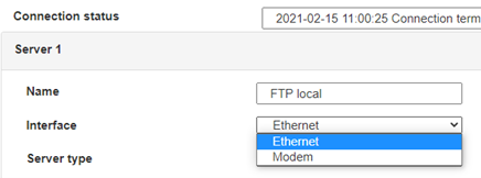
 Geben Sie den Verbindungsmodus „ethernet“ oder „modem“ ein:
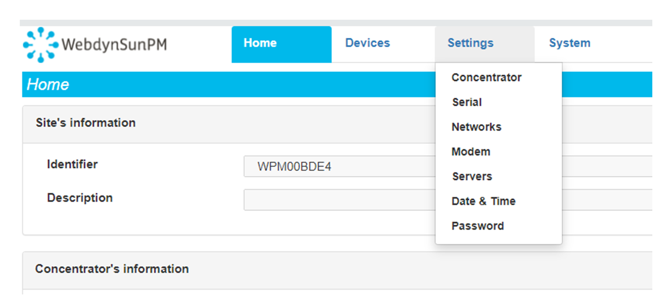
 Stellen Sie bei einer Ethernet-Konfiguration sicher, dass die IP-Parameter mit dem Serverzugriff entsprechend der lokalen Netzwerkkonfiguration des Hubs kompatibel sind. Bei einer Ethernet-Verbindung muss die Konfiguration mit der lokalen Netztopologie des Hubs kompatibel sein, damit dieser auf die Server zugreifen kann. Diese Konfiguration erfolgt über die Konfigurationsseite „Networks“ (siehe Kapitel 3.2.2.3: „Netzwerke (Networks)“).
Bei einer Modemverbindung muss das Modem korrekt konfiguriert sein, bevor eine Verbindung hergestellt werden kann. Diese Konfiguration erfolgt auf der Konfigurationsseite „Modem“ (siehe Kapitel 3.2.2.4: „Modem“).
Die minimal zu konfigurierenden Serverparameter sind folgende:
 Diese Felder müssen konfiguriert werden: „Interface“, „Type“, „Server type“, „Address“, „Port“, „Login“ und „Password“.
In den übrigen Feldern können die Standardwerte beibehalten werden, solange die Verzeichnisse zuvor korrekt angelegt wurden. Weitere Einzelheiten siehe Kapitel 3.1.2: „Konfigurationsdateien“.


 Warten Sie. Der Hub startet nach ein paar Augenblicken mit der Werkseinstellung neu.


