Suchen Sie etwas anderes?
Table of Contents
Scene Details
Titan routers have all the funcionalities a 2G/3G/4G router has, plus a variety of additional features that make it into one of the most functional router in the marketplace.
One of those additional features is the ability of automatically questioning Modbus RTU or TCP devices, and then sending the data to a web, FTP or MQTT server.
As usual, we will illustrate that ability with an easy example.
Example Description
This example shows how to configure a Titan router to read, collect and send modbus registries from 2 PLCs through MQTT. Those readings will happen every 10 minutes.
The modbus registries to be read from PLC1 are:
1;10;11;12;55;56;69;70;72;73;74;75;76;77;78;79;80;100;101;102;103;104;105;106;107;108;109; 120;121;122;123;124;130;131;132;133;152;153;154;160;161;162;163;164;165;166;170
The modbus registries to be read from PLC2 are:
10;11;12;13;14

That is, from PLC1 we are getting a diverse registry map, non-consecutive registries sometimes. PLC2 is more simple and we only need 5 consecutive registries.
The PLCs are RS485 devices, so we will use Modbus RTU, but the scenario also applies to Modbus TCP equipment (with Ethernet) or to both kinds of equipment used simultaneously (Modbus TCP and Modbus RTU).
Configurating Port where Modbus Devices Connect in the Router
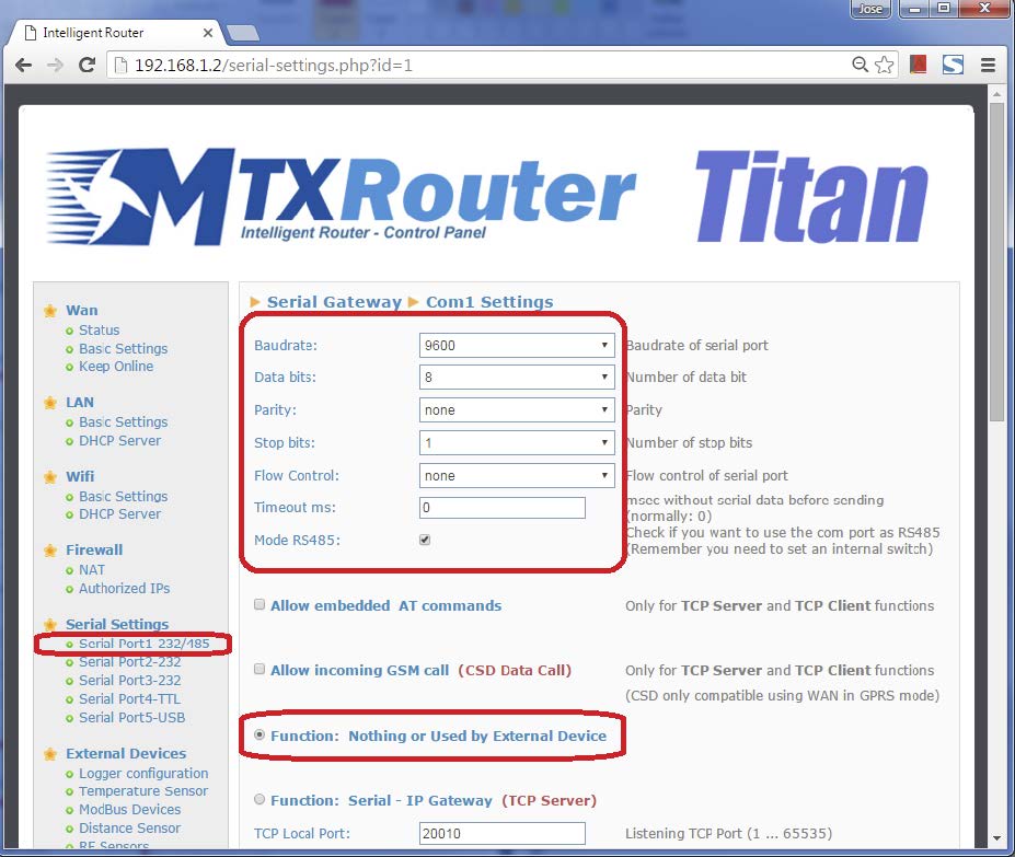
Let’s say the PLCs, with a RS485 port, have the serial port configuration: 9600,8,N,1. Then, our first task is to configure the Titan router serial port COM1, since this port can be configured as an RS232 or RS485 port. The next picture shows how to configure the port COM1.
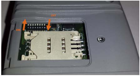
Let’s not forget that in order to activate the BUS RS485 of the MTX-Router-Titan II-3G, we need to activate the microswitches indicated in the user guide (turn on n. 3 and 4 for RS485).
Configuring Titan for the Reading of Modbus Devices
We click on the link: “External Devices > Modbus Devices” and configure the screen as shown below:
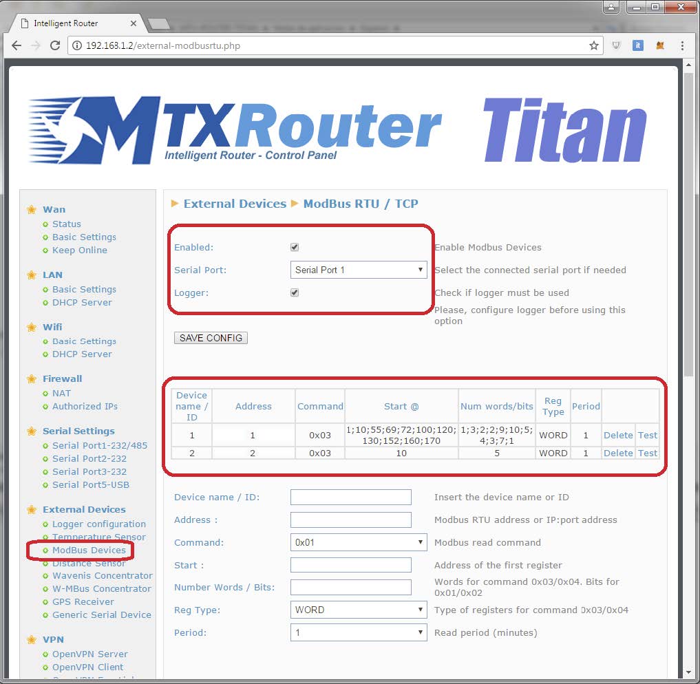
To read registries 10,11,12,13,14 from PLC2, we specify registry “10” in field “Start” and the number “5” in the “Number Words,” since we want to read 5 registries, from 10 to 14. PLC1 is more complex, since it has a non-consecutive registry map. That is why we will separate the registry blocks with a semicolon (;). That is, if we want to read the following registries:
1;10;11;12;55;56;69;70;72;73;74;75;76;77;78;79;80;100;101;102;103;104;105;106;107;108;109; 120;121;122;123;124;130;131;132;133;152;153;154;160;161;162;163;164;165;166;170
… we will enter the initial registry of each block in the field “Start” like this:
1;10;55;69;72;100;120;130;152;160;170
And the number of registries to be read in each block in the field “Number Words” like this:
1;3;2;2;9;10;5;4;3;7;1
Logger Configuration (communication with MQTT server)
The next step is configuring the Logger, that is, the Titan router system that collects and sends the data. This example explains how to configure the router to send the data to an MQTT broker.
We will use the Mosquitto test broker at test.mosquitto.org as a MQTT broker. That is where we will send data of every reading (timestamp, ID equipo…) in JSON format. To do it in a secure way, we will use SSL communications, so we will need Server and Client certificate.
As we can see in the following picture, we will access through the menu “External Devices > Logger Configuration” and will configure that section as shown below:
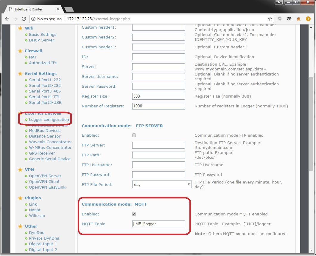
On this screen we have activated the MQTT mode. All data gathered by Titan router will be published in the topic [IMEI]/logger. Note the router will substitute the tag [IMEI] with its real IMEI. That is, if the router IMEI is 357299070082380 (the IMEI can be checked in the menu WAN > Status) the topic used by Titan router to publish the modbus data will be 357299070082380/logger.
Also, if we activate the logger mode, we need to configure the MQTT client in the section Other > Mqtt
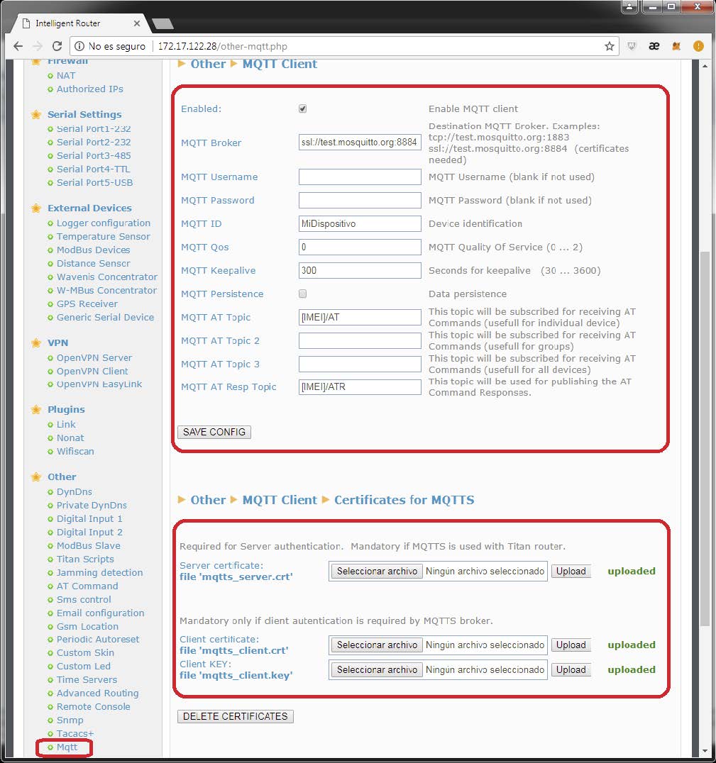
We will activate the Enabled field. In the MQTT Broker field we will write: ssl://test.mosquitto.org:8884, specifying the url of the MQTT broker we want to connect to. In MQTT ID we will write a unique identification for our device (if we connect two devices with the same ID, they will disconnect, since a broker can’t have two devices with the same ID). We can send AT commands to the Titan router (form example, to configure it or to see its status from a mobile phone that is also connected to the MQTT broker) we should fill in the MQTT AT Topic and MQTT AT Response Topic.
All the AT commands sent to the broker to the MQTT AT Topic will be executed by Titan router. Once executed, the result of the AT command will be published by Titan router in the MQTT AT Response Topic.
Next, we will configure the certification section. To do that, it is useful to follow the instructions in: http://test.mosquitto.org/
First we will download the Mosquitto certificate that can be found here: mosquitto.org.crt (PEM format).
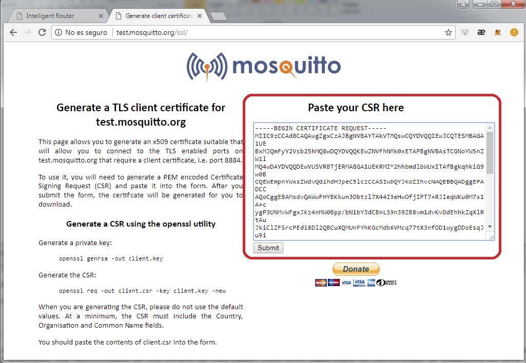
Then we will execute the sentences on this link: http://test.mosquitto.org/ssl/. To do that we will need to install openssl in our computer. We will execute:
openssl genrsa -out client.key
openssl req -out client.csr -key client.key –new
We will have the files client.key y client.csr.
Once we have both files, we copy the content of the file client.csr in the text box and click submit. This way we will obtain the files with the certificate we need client.crt.
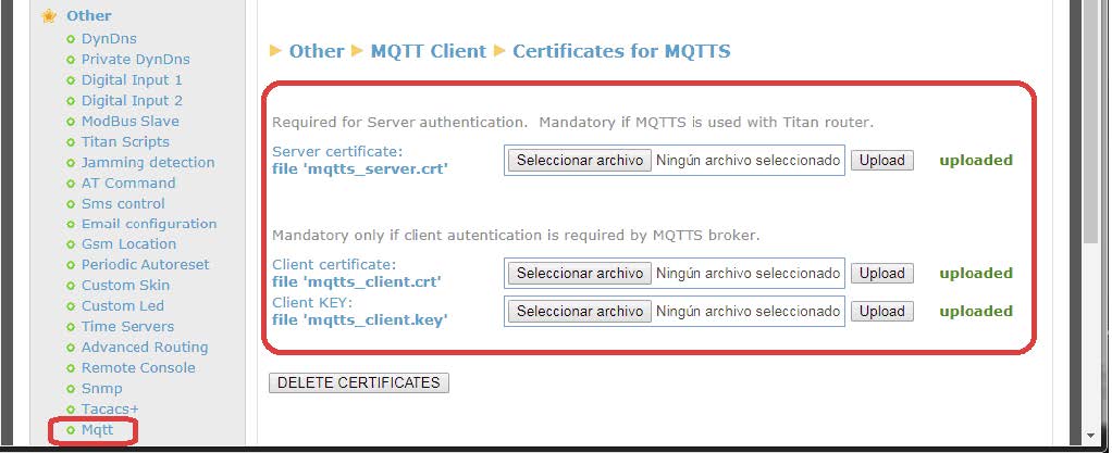
Once we have all three files, mosquitto.org.crt, client.key y client.crt we insert them in the Titan router.
Final Remarks
After configuring the Titan router we need to restart it so it functions with the new configuration and it can start reading and sending data.
Every time the Titan router sends a measurement to an MQTT broker, it does it through the following JSON object:
Example JSON PLC2
{TYPE:MODB,ID:2,TS:17/06/2017 17:01:05,IMEI:357044060009633, P:12345678,A:2,ST:10,N:5,V:[10,11,12,0,0]}
Example JSON PLC1
{TYPE:MODB,ID:1,TS:17/06/2017 17:01:04,IMEI:357044060009633,P:12345678,A:1,STX: [1,10,55,69,72,100,120,130,152,160,170],NX:[1,3,2,2,9,10,5,4,3,7,1], PX:[0,1,4,6,8,1 7,27,32,36,39,46], V:[1,10,11,12,55,56,69,70,72,73,74,75,76,77,78,79,80,100,101,10 2,103,104,105,106,107,108,109,120,121,122,123,124,130,131,132,133,152,153,154, 160,161,162,163,164,165,166,170]}
Where:
TYPE: indicates the kind of data (MODB = Modbus reading)
TS: indicates the Timestamp (that is, the time of the measurement reading)
IMEI: indicates a unique identifier for the modem
P,: in the case of HTTP it indicates the configured ID field
ST: indicates the address of the first registry read
STX: array that indicates the address of the first modbus registries in case a group of
registries is read
N: indicates the number of words read
NX: array that indicates the number of words read in case a group of registries is read
PX: array that indicates the position of the initial registry of each block inside V
V: array with the read data
Note there is a significant difference between the data sent by PLC1 and PLC2. PLC1 has groups, thus fields “ST” and “N” are substituted in JSON by “STX” and “NX,” arrays that store the initial registries and registry numbers of each block. Also, the “PX” registry indicates the initial position of the group inside array “V”. In fact, PX is not necessary since it can be calculated, but it is included to facilitate the decoding operation in the server.
Communication with Router via AT Commands Sent through MQTT
As said before, we can send AT commands to Titan router via MQTT, in order to change a configuration, check on the coverage, reset the router, commute a relay, etc.
For example, if we want to check the coverage, we can use myMQTT software for Android, sending AT+CSQ command to the topic [IMEI]/AT, which in the case of this example is 357299070082380/AT.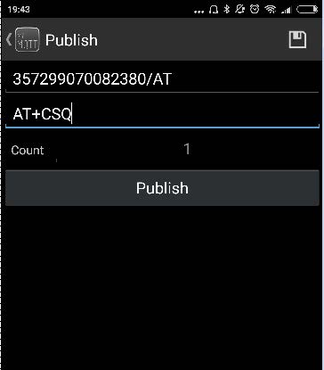
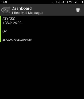
Once we push “Publish,” the command will be received and executed by Titan router. The response will be published by Titan router in the topic 357299070082380/ATR, as we configured it beforehand.


 Enter the “ethernet” or “modem” connection type:
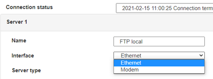 For an ethernet configuration, make sure the IP parameters are compatible with server access according to the concentrator local network configuration. For an ethernet connection, the configuration must be compatible with the concentrator’s local network topology so that it can access the servers. This configuration is done from the “Networks” configuration page (see section 3.2.2.3: “Networks”).
For a modem connection, the modem configuration must be correct before a connection can be set up. This configuration is done from the “Modem” configuration page (see section 3.2.2.4: “Modem”).
The parameters for the servers to be configured are at least the following:
 Therefore the following fields need to be configured: “Interface”, “Type”, “Server type”, “Address”, “Port”, “Login” and “Password”.
The other fields can be left at the default values subject to the directories having been properly created beforehand. See section 3.1.2: “Configuration files” for more details.


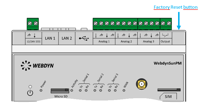 Wait. The concentrator will reboot using its factory configuration.

